1.800.627.4499
14
Integral Indirect Gas-Fired Heat Module
OPTION
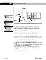
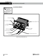
2.1.3 Outdoor Module Venting
Outdoor modules must be individually vented.
The venting system is designed for direct discharge of flue gases to the outdoors. The vent
discharge opening should be located to provide an unobstructed discharge to the outside and
should be located as far from the combustion air as possible, but in the same pressure zone.
FIGURE 2.1.4 OUTDOOR HORIZONTAL VENTING
Combustion
Air Exhaust
Combustion
Air Intake
Roof Deck or
Equipment Pad
Curb or Equipment Rails
RenewAire LLC
SCALE:1:30
SIZE
DWG. NO.
A
MATERIAL:
FINISH:
SEE BILL OF MATERIAL
DO NOT SCALE DRAWING.
REMOVE ALL BURRS, BREAK
SHARP EDGES.
APPLICABLE STANDARDS: DIM.
AND TOL. ANSI Y14.5
UNLESS OTHERWISE SPECIFIED,
DIMENSIONS ARE IN INCHES.
TOLERANCES:
LINEAR 0.015
HOLE SIZE 0.005
ANGULARITY 3
SURFACE FINISH =
63 MICROINCH MINIMUM
DATE:
DRAWN BY:
CAH
10/29/18
DN RT GH Horiz Vent
OCT18
SHEET 1 OF 1
4510 Helgesen Dr.
Madison, WI 53718 USA
TEL: (608) 221-4499
FAX: (608) 221-2824
TOLL FREE: (800) 627-4499
TITLE:
CHECKED BY:
DATE:
--
--
DN-3-RT GH HORIZONTAL VENT
LEVEL DESCRIPTION OF REVISION
DATE
BY
-
-
-
-
-
SEE BILL OF MATERIAL
2.2 GAS SUPPLY
Installation of piping must conform with local building codes and ordinances, or, in the absence
of local codes, with ANSI Z223.1, the National Fuel Gas Code. In Canada, installation must be in
accordance with CAN/CGA-B149 for natural gas and B149.2 for propane units.
Gas piping must be sized for the total BTU input of all modules serviced by a single supply.
Be sure that gas regulators servicing more than one modules have the proper pipe and internal
orifice size for the total input of all modules serviced by the regulator.
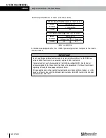
See table below for minimum inlet gas pressure required and maximum permissible supply
pressure at each module.
Natural Gas
Propane Gas
Minimum (50 to 350 MBH models):
5.0 InWC
11.0 InWC
[14,653 to 102,574 W]
[1244 Pa]
[2737 Pa]
Maximum Inlet Pressure:
13.5 InWC
13.5 InWC
[3359
Pa]
[3359
Pa]
Connect a fitting suitable for connection to a pressure gauge capable of measuring gas
pressure to 1/8” NPT tap provided on the inlet side of the gas valve or manual shut-off tapping.
Measure inlet pressure to each module serviced by a single regulator with all modules in
operation.
Gas supply piping to multiple modules should be configured to provide equal pressure to all
modules. With all modules operating at full output, minimum supply gas pressure should be
checked at all modules.
A drip leg (sediment trap) and a manual shut off valve must be provided immediately upstream
of the gas control on the heating unit. To facilitate servicing of the unit, installation of a union is
recommended.
All gas supply and furnace connections must be leak tested prior to placing equipment in
service.
SYSTEM REQUIREMENTS


