1.800.627.4499
34
Integral Indirect Gas-Fired Heat Module
OPTION
4.00
2.00
DETAIL A
SCALE 1 : 8
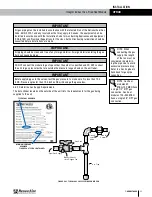
PLUG
TEE FITTING
STAINLESS STEEL
TRAP LINE
RenewAire LLC
SCALE:1:24
SIZE
DWG. NO.
A
MATERIAL:
FINISH:
SEE BILL OF MATERIAL
DO NOT SCALE DRAWING.
REMOVE ALL BURRS, BREAK
SHARP EDGES.
APPLICABLE STANDARDS: DIM.
AND TOL. ANSI Y14.5
UNLESS OTHERWISE SPECIFIED,
DIMENSIONS ARE IN INCHES.
TOLERANCES:
LINEAR 0.015
HOLE SIZE 0.005
ANGULARITY 3
SURFACE FINISH =
63 MICROINCH MINIMUM
DATE:
DRAWN BY:
CAH
10/29/18
DN RT GH
Draintrap OCT18
SHEET 1 OF 1
201 Raemisch Rd.
Waunakee, WI 53597 USA
TEL: (608) 221-4499
FAX: (608) 221-2824
TOLL FREE: (800) 627-4499
TITLE:
CHECKED BY:
DATE:
--
--
DN-3-RT GH CONDENSATE DRAIN
LEVEL DESCRIPTION OF REVISION
DATE
BY
-
-
-
-
-
SEE BILL OF MATERIAL
A manual shut-off valve (gas cock), a 1/8 inch plugged test port or bleeder valve and a drip leg
must be field-installed between the gas supply pipe and the start of the gas train. The valve and
test port must be accessible for the connection of a test gauge. Supply gas connections must
be made by a qualified installer and are to be provided by others.
Connect gas supply piping to the gas fitting on the front of the module. Follow all local codes,
or, in the absence of any local codes, comply with ANSI Z223.1.
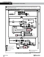
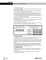
5.9 CONNECT CONDENSATE DRAIN
Each ducted gas module is equipped with a 3/8 inch diameter stainless steel condensate drain
tube that extends from the front of the module. The condensate drain tube is under negative
pressure and must be trapped. The trap is to be provided by others and field-installed. The trap
should be fabricated in accordance with local building codes. It should allow for easy cleaning
and easy addition of a glycol solution, if needed for winterization. In addition, attention should
be given to the possible need for heat tapes. If heat tapes are to be used, it may be necessary
to fabricate the trap and other drain piping from metal.
The drain trap should be filled with water or glycol solution prior to module start-up.
OPERATION
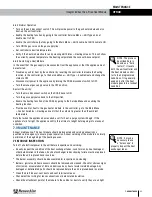
FIGURE 5.9.0 RECOMMENDED DRAIN TRAP CONSTRUCTION
6.0 OPERATION
6.1 GAS HEATER QUICK-START GUIDE
A wiring diagram and a Sequence of Operation are provided in the unit information package
for each specific control system provided on the heat module. Refer to the documents before
attempting to place the unit in service.
u
This heat module does not have a pilot light. It is equipped with a direct spark ignition device
that automatically lights the gas burner. DO NOT try to light burners by hand.
u
BEFORE OPERATING, leak test all gas piping up to the heater valve. Smell around the unit
area for gas. DO NOT attempt to place the unit in operation until source of gas leak is
identified and corrected.
u
Use only hand force to push and turn the gas control knob to the “ON” position. NEVER use
tools. If knob does not operate by hand, replace gas valve prior to starting the unit. Forcing or
attempting to repair the gas valve may result in fire or explosion.
u
Do not attempt to operate the module if there is indication that any part or control has been
under water. Any control or component that has been under water must be replaced prior to
trying to start the module.
The gas heat module requires both high-voltage power and a low-voltage control signal. High-
voltage power is present whenever the DN-Series disconnect switch is turned on. The control
signal is provided by the DN-Series Integrated Programmable Controller.
NOTE: Start-Up
is defined as the
process of activating
each system within a new-
ly-installed module after it
has been properly installed
in the system in which it is
expected to operate. A full
and proper start-up cannot
be performed unless the
Occupied Space with all its
associated ductwork, con-
trols and design options
are completed and intact
and ready for full-load
testing.

