37
1.800.627.4499
Integral Indirect Gas-Fired Heat Module
OPTION
6.2.5 Verify That Heater Settings Will Call For Heat
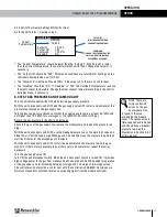
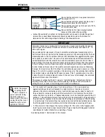
Go to the Unit Status > Heating screen.
Current
Temperature
SETPOINT
(MUST BE GREATER THAN
CURRENT TEMPERATURE)
COMMAND
(SHOWS THE STRENGTH OF THE
CALL FOR HEAT SIGNAL AS A
PERCENTAGE OF 10 VDC)
Unit Status
Setpoint
79.00 F
78.60 F
Command
100.0
0
%
HEATING
Output ON
YES
Disabled
NO
u
The “Current Temperature” should be lower than the “Setpoint”. If the Setpoint is lower
than the Current Temperature, the controller will not call for heat. Change the setpoint, if
necessary.
u
The “Output ON” should be “YES”. This means conditions are favorable for heating and the
controller should provide a call for heat.
u
The “Command” is between 0% and 100%. If the value is 0%, there is no call for heat.
u
The “Disabled” should be “NO”. If “Disabled” is “YES”, the Outside Air temperature is above
the Heat Lockout temperature. Change the Heat Lockout temperature setting in the Control
Variables menu, if necessary.
6.3 TEST GAS PRESSURES AND FLAME QUALITY
Turn the unit disconnect switch OFF while testing gas supply pressure.
With the unit disconnect switch OFF and the gas supply valve OFF, install a manometer at the
pressure tap located on the gas supply line.
Turn the gas supply valve ON and verify that the supply gas pressure is at least 5.0 InWC and
not higher than 13.5 InWC for natural gas or 11.0 InWC to 13.5 InWC for LP gas.
Record the gas pressure in the chart on next page.
Shut off the gas at the gas supply line, remove the manometer and replace the pressure tap
plug.
With the unit disconnect switch OFF, use the bleeder/pressure tap on the main inlet valve and
bleed the air from the supply pipe. When gas can be smelled, close the pressure tap and then
wait five minutes for the escaped gas to dissipate.
With the unit disconnect switch OFF, install the manometer on the pressure tap on the gas
manifold. If there are two pressure taps, either use two manometers or repeat the test as
necessary.
Turn the gas supply valve ON.
Turn ON the unit disconnect switch. When the unit disconnect switch is turned ON, it provides
high-voltage power to the gas heat module and will also produce 24 VAC needed for operation
of the gas valves and for switching between 1st stage and 2nd stage on two-stage valves.
The controller will not provide a call for heat until the controller is ENABLED. Gas valves are
Normally Closed (NC) until they receive an activating signal from the module controller.
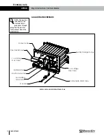
NOTE: There are
two gas shut-off
valves on the gas
heat module. One
is found in the mod-
ule, behind the module
cover. The second valve is
field-supplied and installed
and should have a bleeder/
pressure tap. See the
illustration in Section 5.8.2
of this manual.
OPERATION

