9
1.800.627.4499
Integral Indirect Gas-Fired Heat Module
OPTION
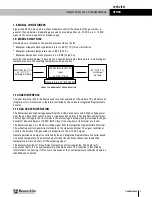
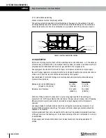
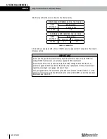
FIGURE 1.9.0 MODULE HEAT RISE CALCULATION
4939 CFM [2331 l/s]
45 ˚F [7.2 ˚C]
Entering Air Temp
300,000 Btuh [87,921 W]
Input
45 ˚F [25 ˚C] Rise
90 ˚F [32.2 ˚C]
Discharge
Air Temp
Pressure Drop .22" WC [54 Pa]
1.8 SIGNAL CONDITIONERS
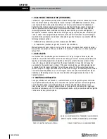
Signal conditioners are used in all heat modules to control the outputs of the gas valves. In
general, they modulate a modulating gas valve by providing either a 0–10 VDC or a 2–10 VDC
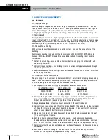
signal to the valve. See photo on previous page.
1.9 MODULE HEAT RISE
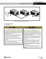
All modules are installed on the positive pressure side of the fan.
u
Maximum allowable discharge temperature is 160˚F [71˚C] for any installation.
u
Maximum allowable temperature rise is 60˚F [33.3˚C]
u
Maximum design duct static pressure is 3.0 InWC [746.5 Pa].
Note that the example below is based upon a specific Entering Air temperature. As Entering Air
temperatures vary, the resulting temperature rise also varies.
1.10 USER INTERFACE
The User Interface (U/I) is the device used to control operation of the module. This module is an
integral part of a DN unit and is therefore controlled by the on-board Integrated Programmable
Control.
1.11 GAS HEATER OPERATION
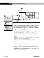
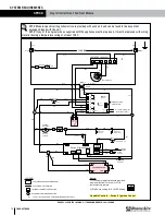
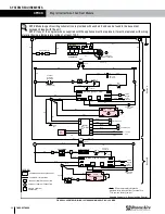
The heater receives high-voltage power from the DOAS disconnect switch. High-voltage power
from the unit disconnect switch runs to a step-down transformer in the gas heat compartment.
Primary input voltage to the transformer is the unit voltage. Secondary output voltage to the gas
heat draft inducer blower is 115 VAC. Both sides of the step-down transformer are fused.
The heater receives a 0–10 VDC activating signal from the Integrated Programmable Controller.
The activating control signal wires terminate on the signal conditioner. The signal conditioner
controls the output of the gas valves in proportion to the 0–10 VDC signal.
Heater operation and output is controlled by the unit Integrated Programmable Controller based
on desired temperature. The heater shuts off when the controller senses that the desired
temperature is met and shuts off the activating signal.
The heater will switch off if insufficient combustion airflow is detected. The heater will
also switch itself off if an over-temperature condition occurs. This condition is identified by
intermittent or no heating. If this occurs, the cause of the over-temperature condition should be
identified and corrected.
OVERVIEW


