Operator Unit
130--613
Operator Unit
73
Edition: Sept. 10, 2005
3648/130--613.DOC010102
6.3.2.4
Gyro Data
With this sub--menu the essential operating data of all connected Gyros (max. three) are
displayed.
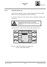
Select line “Menu” with the softkeys “Select Sensor & Menu” and ”Set”.
Select line “Service” with the softkeys “Select Menu” and “Set” in the following display.
Select “Next Page” with the softkeys “Select Menu” and “Set” in the display
“Service Mode (page1).
Select line “Gyro Data” with the softkeys “Select Menu” and “Set” in the display
“Service Mode (page2).
Dim
Up
Dim
Down
Gyro Data
Set
Select
Gy1/15
Gy2/16
Temperature
: 49.7
°
----.--
°
Gyro Supply
: 54.9V
----.--V
Gyro Current
: 213mA ------mA
Pump Supply
: 22.7V
----.--V
Pump Current
: 155mA ------mA
Sensor PCB
: OK
--
Power PCB
: OK
--
Gyro PCB
: OK
--
Connect. PCB : OK
--
Set Service Timeout to 120s
Exit
Service Timeout in xxxs
Figure 72: Controls and Indicators on the Operator Unit
(Sub menu “Gyro Data” selected)
Two Gyros connected, one with an older development status
Parameter
Meaning
Gy1/15
Gyro 1 with Can--bus address 15
Temperature
Temperature of the supporting liquid
Gyro Supply
Supply voltage of the gyrosphere
Gyro Current
Current consumption of the gyrosphere
Pump Supply
Supply voltage of the pump
Pump Current
Current consumption of the pump
Sensor PCB
OK* = no error message of the Sensor PCB
Power PCB
OK* = no error message of the Power PCB
Gyro PCB
OK* = no error message of the Outer Sphere PCB
Connect. PCB
OK* = no error message of the Connection PCB
*Failure = Error at the respective PCB


