Operator Unit
130--613
4
3648/130--613.DOC010102
Edition: March 11, 2005
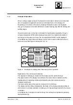
A two-colour LED is positioned above the red membrane key. This LED indicates
alarms and their status. It also serves to indicate when selected data has been
transferred to the CAN bus. (the “SET” soft key).
See section 2 of this manual for further information about the controls and indicators.
Dim
up
Dim
down
Magnet
068.7
°
HEADING
Gyro 1
067.9
°
Gyro 2
069.0
°
Gyro 3
068.9
°
Contrast
Vari--
ation
Select
Sensor
& Menu
Devi--
ation
Deviation:
03.0
°
Variation:
04.0
°
Gyro/Mag Diff: 03.0
°
Lamp
Test
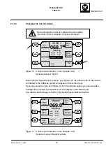
Figure 3:
Example of the display when the “Magnetic Sonde” sensor is selected
All equipment and sensors connected to the CAN bus take the data they require for their
particular function from the CAN bus.
The selected sensor leads the heading information
to all connected receivers via the CAN bus.
But not each heading receiver is allowed to use head-
ing information from a magnetic compass if selected.


