Operator Unit
130--613
Operator Unit
3
Edition: March 11, 2005
3648/130--613.DOC010102
1.1.1
Principle of Operation
Once a voltage supply is present, the Operator Unit is able to detect every connected
item of navigational equipment (sensors) and indicate them on the display unit.
Depending on the status of the device, heading information is also now displayed.
Any gyro compasses connected will deliver a usable heading only after the heating and
settling stages.
If several sensors are connected, in principle the heading data supplied by the gyro
compass designated GYRO will be displayed (provided it is enabled and usable); if
several gyro compasses are in use, the one designated GYRO 1 will be displayed.
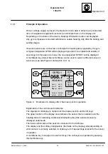
A membrane key (Select Sensor & Menu) can be used to select a different sensor or
sub-menu (see also Figure 3 and section 2.2.1.4).
Dim
up
Dim
down
GYRO 1
068.7
°
HEADING
Aut Spd: 08.5Kts
Aut Lat.: 50
°
05‘
Gyro 2
067.9
°
Gyro 3
068.0
°
Magnet 069.0
°
Select
Speed
Select
Sensor
& Menu
Select
Lat.
Contrast
Lamp
Test
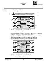
Figure 2:
Example of a display after it has been put into operation
Explanation of the controls and indicators:
The Operator Unit display is divided into the display section and 6 soft keys.
The upper section of the display area indicates the sensor that is selected, and the
heading data it is indicating. Additional information about the selected sensor is
displayed underneath.
The lower section lists all the sensors connected to the CAN bus.
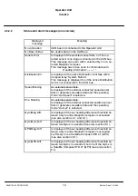
The display and the softkey designations (the fields on the display) alter depending on
which sensor is currently selected, to enable you to make settings relevant to the sensor
in question.
A membrane key is assigned to each soft key. The soft keys are operated by pressing
this membrane key.


