53
0750-M001-0
4.15
Fissaggio al suolo delle colonne
Con riferimento alla
Fig.21
:
- Posizionare la pedana a circa 1’ (30 cm) da terra.
- Montare i pattini di guida (
1
): tali pattini devono aderire ai bordi delle colonne e pertanto può essere necessario un aggiustaggio
degli stessi.
NOTA
: I pattini di guida (
1
) sono presenti solo nelle traverse monolitiche, come evidenziato in figura. I pattini non sono presenti
sulle semitraverse.
- Premere il pulsante di salita (
4
) ed effettuare una corsa completa: durante tale corsa è bene controllare (eventualmente
fermandosi ogni 8” - 1’ (20-30 cm) che lo scorrimento sulle aste asolate avvenga regolarmente e senza anomali sfregamenti:
se si verificano malfunzionamenti è opportuno rivedere la messa a piombo delle colonne.
- Liberare il dispositivo paracadute e la camma controllo funi togliendo le fascette (
2-3
) ed effettuare una corsa completa di salita
e discesa; con piattaforma a terra procedere quindi alla foratura del terreno (fori Ø 23/32” e profondità 2 3/8") (fori Ø 18 mm
e profondità 60 mm) centrandosi nei fori delle basi delle colonne
- Inserire poi i tasselli in dotazione e bloccare a fondo.
4.16
Registrazione microinterruttori di sicurezza sulle funi
ESEGUIRE SEMPRE LA SEGUENTE REGISTRAZIONE:
Sollevare le pedane a circa 5’ (m. 1,5) da terra; premere il pulsante di stazionamento e fare scendere le pedane in appoggio nelle
asole delle aste asolate.
Premendo il pulsante di discesa la elettrovalvola
EV3
non si deve eccitare. Eventualmente riposizionare e regolare i microinterruttori
FC1÷FC4
in modo che questo accada.
4.15
Anchoring the posts
Please refer to
Fig.21
:
- Place platform about 1’ (30 cm) above ground.
- Install the slide guides (
1
). Slide guides must adhere to post contour and it may be necessary to machine them.
NOTE
: Sliding guides (
1
) are present only on monobloc cross members, as shown in the figure. They are not fitted on semi-cross
members.
- Press the up button (
4
) and run a full stroke. While platform is moving, check that it slides smoothly along the racks and that no
abnormal friction occurs at any position. You might want to stop the platform every 8” - 1’ (20-30 cm) in order to check more
accurately. In the event of malfunction, check that posts are perfectly vertical.
- Remove clips (
2-3
) to release the safety lock system and the cable control cam. Raise the lift fully and then lower it. With the platform
lowered to the ground, drill 23/32” diam. holes 2 3/8" deep (18 mm diam. holes 60 mm deep) into the flooring. Holes must be
centred to the holes in the post feet.
- Insert the supplied expansion bolts and tighten securely in place.
4.16
How to adjust the safety microswitches on cables
ALWAYS ACT AS FOLLOWS:
Lift the platforms about 5’ (1.5 m) away from ground; press the parking button and lower platforms against the rod slots.
EV3
solenoid valve should not be activated when downstroke button is being pressed. Reposition and adjust the microswitches
FC1÷FC4
if necessary.
Summary of Contents for 0750-M001-0
Page 9: ...SAFETY WARNING LABELS for Four Post Surface Mounted Roll on Lifts...
Page 10: ......
Page 11: ......
Page 14: ...0750 M001 0 14 Fig 2 1 1 G 14000 lbs...
Page 24: ...0750 M001 0 24 Fig 7...
Page 34: ...0750 M001 0 34 18 14 18 15 16 18 18 7 G Fig 12...
Page 36: ...0750 M001 0 36 Fig 13 5 4 6 8 9 7 1 3 2 10...
Page 38: ...0750 M001 0 38 Fig 14 7 8 6 3 4 5 1 3 2 10 11 9 3...
Page 40: ...0750 M001 0 40 Fig 15 1 5 2 4 3 3 1...
Page 42: ...0750 M001 0 42 Fig 16 EV3 2 A B C 1 3 4 6 D D EV3 E 7 7 9 8 5 10...
Page 48: ...0750 M001 0 48 Fig 19 1 2 3...
Page 52: ...0750 M001 0 52 1 3 2 4 Fig 21...
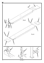
Page 54: ...0750 M001 0 54 Fig 22 3 1 5 5 5 4 4 5 2 6 Fig 23 1 2 3 2 1 3 2 2 Fig 24 4 5 6...
Page 60: ...0750 M001 0 60 2 Fig 25 1 3 4...
Page 62: ...0750 M001 0 62 Fig 27 Fig 26 3...
Page 99: ...99 99 0750 M001 0 NOTE NOTES...


