31
0750-M001-0
4.4
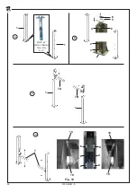
Montaggio della piattaforma
Con riferimento alla figura
10
:
A) Posizionare e fissare al pavimento le colonne anteriori (
1
) tramite gli appositi tasselli, dopo avere eseguito le forature Ø 5/8”
x profondità 4” (diametro 16 mm - profondità 100 mm) come illustrato in
Fig. 10
. Occorre rispettare in particolar modo le quote
E2
(toll/- 3/64” (+/- 1 mm)),
F
,
F2
,
G2
. Al termine di questa operazione è importante verificare la perpendicolarità di
ciascuna colonna (
1
) rispetto al pavimento, spessorando dove neccessario le piastre di base (toll/- 3/64” (+/- 1 mm)).
B) Su entrambe le colonne (
1
) rimuovere:
- il carter di copertura,
- l’asta asolata (
2
), la protezione salvadita (
3
), il blocchetto (
4
) e le piastre superiori (
5
) e (
6
).
C) Inserire le semitraverse (
7A
e
7B
) dall’alto delle colonne (1).
Prestare attenzione:
la traversa (
7B
), dotata dei fori per il fissaggio della camma finecorsa, deve essere installata sulla colonna
comandi.
D) Fare scorrere verticalmente ciascuna semitraversa (
7
) lungo la colonna ed identificare il punto di minima distanza tra i pattini
(
8
) ed i tubolari (
9
).
Inserire appositi spessori (
10
) dietro ai pattini (
8
) per ridurre al minimo il gioco rispetto ai tubolari (
9
).
4.4
Platform installation
Refer to figure
10
:
A) After having carried out the necessary holes Ø 5/8” x depth 4” (diameter 16 mm - depth 100 mm) as shown in
Fig. 10
, set and
secure to floor front posts (
1
) by means of the suitable anchors. The following values shall be complied with:
E2
(tol/
- 3/64” (+/- 1 mm)),
F
,
F2
,
G2
. Once this operation is completed, it is necessary to check that each post (
1
) is at right angles to
the floor, shimming, where needed, the base plates (tol/- 3/64” (+/- 1 mm)).
B) Remove on both posts (
1
):
- cover,
- slotted bar (
2
), finger guard (
3
), block (
4
) and upper plates (
5
) and (
6
).
C) Fit semi-cross members (
7A
and
7B
) from posts (
1
) upper side.
Warning:
the cross member (
7B
), provided with the suitable holes for the limit switch cam fastening, shall be installed onto the
control post.
D) Vertically slide each semi-cross member (
7
) along the post and identify the minimum distance point between sliding shoes (
8
)
and tubular structures (
9
).
Fit suitable shims (
10
) behind sliding shoes (
8
) in order to reduce to a minimum the clearance with respect to tubular structures
(
9
).
Summary of Contents for 0750-M001-0
Page 9: ...SAFETY WARNING LABELS for Four Post Surface Mounted Roll on Lifts...
Page 10: ......
Page 11: ......
Page 14: ...0750 M001 0 14 Fig 2 1 1 G 14000 lbs...
Page 24: ...0750 M001 0 24 Fig 7...
Page 34: ...0750 M001 0 34 18 14 18 15 16 18 18 7 G Fig 12...
Page 36: ...0750 M001 0 36 Fig 13 5 4 6 8 9 7 1 3 2 10...
Page 38: ...0750 M001 0 38 Fig 14 7 8 6 3 4 5 1 3 2 10 11 9 3...
Page 40: ...0750 M001 0 40 Fig 15 1 5 2 4 3 3 1...
Page 42: ...0750 M001 0 42 Fig 16 EV3 2 A B C 1 3 4 6 D D EV3 E 7 7 9 8 5 10...
Page 48: ...0750 M001 0 48 Fig 19 1 2 3...
Page 52: ...0750 M001 0 52 1 3 2 4 Fig 21...
Page 54: ...0750 M001 0 54 Fig 22 3 1 5 5 5 4 4 5 2 6 Fig 23 1 2 3 2 1 3 2 2 Fig 24 4 5 6...
Page 60: ...0750 M001 0 60 2 Fig 25 1 3 4...
Page 62: ...0750 M001 0 62 Fig 27 Fig 26 3...
Page 99: ...99 99 0750 M001 0 NOTE NOTES...


