33
0750-M001-0
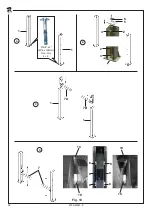
E) Verificare il parallelismo di ciascuna semitraversa (
7
) rispetto al pavimento (toll/- 3/64” (+/- 1 mm)) sulla quota verticale
(
H
) misurata nei due punti estremi della semitraversa).
PROCEDURA ECCEZIONALE
Nel caso non fosse rispettata la tolleranza sulla quota (H), occorre agire su entrambi i lati della semitraversa. Svitare le
viti (11), inserire appositi spessori (12) nella parte posteriore del supporto rullo (13), avvitare le viti (11).
F) Posizionare le due semitraverse anteriori (
7
) e la traversa posteriore (
14
) su appositi cavalletti alti circa 2’÷ 2’ 4” (60-70 cm),
rispettando la quota “
A
” di distanza tra le traverse.
Posizionare la pedana fissa (
15
) e la pedana mobile (
16
) sulle traverse, mantenendole sollevate dalle stesse di circa 13/16”
(2 cm).
Liberare le funi
F1-F2-F3-F4
, il tubo di recupero olio proveniente dal pistone idraulico di comando ponte, il tubo pneumatico
di azionamento martelletti ed il tubo pneumatico di comando sgancio arpioni del sollevatore integrato.
Smontare le viti di antiscarrucolamento (
17
). Posizionare le funi
F1-F2-F3-F4
all’interno delle testate delle traverse,
alloggiandole nelle gole delle pulegge, seguendo le schema allegato.
Rimontare le viti di antiscarrucolamento (
17
).
Svolgere i cavi elettrici e pneumatici collocati nelle traverse (
7
) e (
14
) ed inserirli nelle pedane.
E) Check the parallelism of each semi-cross member (
7
) with respect to the floor (tol/- 3/64” (+/- 1 mm)) on the vertical
value (
H
): reading taken at the two utmost points of the semi-cross member).
SPECIAL PROCEDURE
In case the tolerance on value (H) is not complied with, it will be necessary to work on both semi-cross member sides.
Undo screws (11), fit the suitable shims (12) at the back of roller support (13), then tighten screws (11).
F) Place the two front semi-cross members (
7
) and the rear cross member (
14
) on suitable stands measuring about 2’÷ 2’ 4” (60-
70 cm) in height, complying with value “
A
” (distance between cross members).
Place the fixed platform (
15
) and the mobile one (
16
) onto the cross members and keep them at a distance of about 13/16” (2
cm) from the cross members. Release cables
F1-F2-F3-F4
, the oil drain hose coming from the hydraulic piston which controls
the lift, the pneumatic hose controlling the catches and that one controlling the lift table hook release.
Remove anti-fleet screws (
17
). Place cables
F1-F2-F3-F4
inside the cross member headers, into the pulleys grooves, as shown
in the enclosed diagram. Fit again anti-fleet screws (
17
). Unwind the electric and pneumatic cables set into cross members (
7
)
and (
14
) and insert them into the platforms.
Summary of Contents for 0750-M001-0
Page 9: ...SAFETY WARNING LABELS for Four Post Surface Mounted Roll on Lifts...
Page 10: ......
Page 11: ......
Page 14: ...0750 M001 0 14 Fig 2 1 1 G 14000 lbs...
Page 24: ...0750 M001 0 24 Fig 7...
Page 34: ...0750 M001 0 34 18 14 18 15 16 18 18 7 G Fig 12...
Page 36: ...0750 M001 0 36 Fig 13 5 4 6 8 9 7 1 3 2 10...
Page 38: ...0750 M001 0 38 Fig 14 7 8 6 3 4 5 1 3 2 10 11 9 3...
Page 40: ...0750 M001 0 40 Fig 15 1 5 2 4 3 3 1...
Page 42: ...0750 M001 0 42 Fig 16 EV3 2 A B C 1 3 4 6 D D EV3 E 7 7 9 8 5 10...
Page 48: ...0750 M001 0 48 Fig 19 1 2 3...
Page 52: ...0750 M001 0 52 1 3 2 4 Fig 21...
Page 54: ...0750 M001 0 54 Fig 22 3 1 5 5 5 4 4 5 2 6 Fig 23 1 2 3 2 1 3 2 2 Fig 24 4 5 6...
Page 60: ...0750 M001 0 60 2 Fig 25 1 3 4...
Page 62: ...0750 M001 0 62 Fig 27 Fig 26 3...
Page 99: ...99 99 0750 M001 0 NOTE NOTES...


