A
BOUT
THE
S
ERVER
CATERR#
1-79
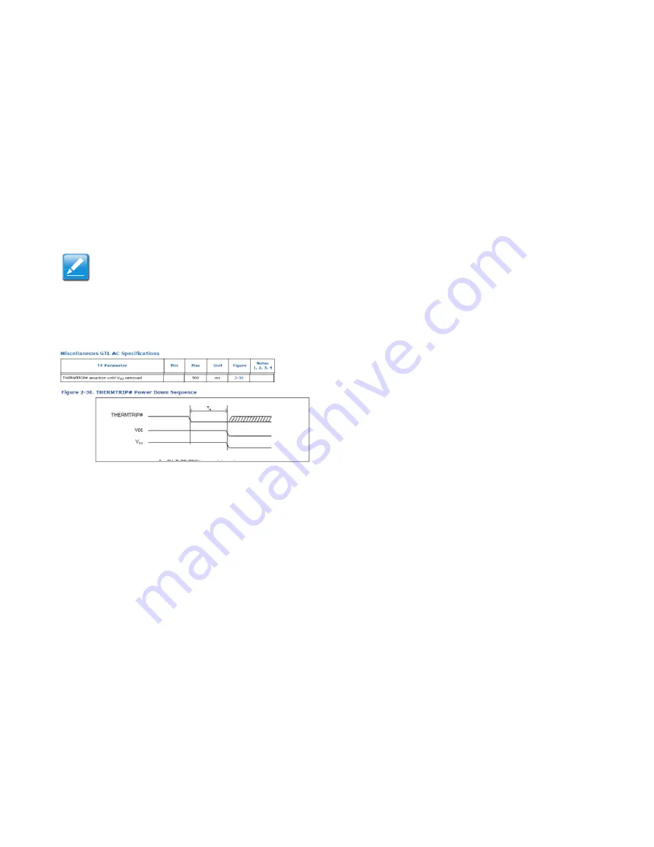
[1.3.220] THERMTRIP# Timing Diagram
[1.3.221] CATERR#
[1.3.222]
The CATERR# signal from the SNB-EP / IVB-EP Pro-
cessor signals that there has been a catastrophic error. Two
types of issues may be signaled by CATERR#. One type is a
warning and is indicated by a 16 BCLK period pulse on the
CATERR# signal. The other is the static critical error which is
indicated by a continuously asserted level on the signal. The
ASPEED AST2300 BMC only logs the static Critical Error
events and it ignores the warnings indicated by the pulse. An
error on the SNB-EP / IVB-EP Processor is immediately com-
municated to the Patsburg SSB, for notification and SMI han-
dler generation. The CATERR# signal must be interconnected
between processors without any logic in its path in order to
achieve the tight timing requirements of this signal. The
CATERR# signal must be isolated and voltage translated
before being connected to the Patsburg Server South Bridge
and the ASPEED AST2300 BMC.
[1.3.223]
The ability to capture this signal at the ASPEED
AST2300 BMC requires that the input filters on the GPIO be
turned off and the GPIO placed into event capture mode.
[1.3.224]
The CATERR# and ERR [1] # signals must be buff-
ered through individual 400usec delay circuits before being
connected to their corresponding Patsburg SSB GPIO signals.
This is due to an erratum on the Sandy Bridge-EP processor
where an MCA event and SMI handler execution race condition
might occur. This is a platform requirement. Refer to the Rom-
ley Common Core System GPIO architecture.
Note:
[1.3.219]
A delay circuit (10ms +/- 25%, based on the fact
that the SGPIO bus is running at 100Mhz/4 and one shift
cycle take 80 clocks) must be incorporated on the
THERMTRIP_N signal before the signal is connected to the
Patsburg SSB THERMTRIP_N pin. This is required so that
the ASPEED AST2300 controller can sample the event
before the system shuts down
Summary of Contents for W Mainboard Series S210-MBT2W
Page 25: ... 1 0 1 About the Server Chapter 1 ...
Page 31: ... 1 3 31 Functional Architecture ...
Page 121: ... 2 0 1 BIOS Chapter 2 ...
Page 187: ... 3 0 1 BMC Chapter 3 ...
Page 265: ... 4 0 1 Jumpers and Connectors Chapter 4 ...
Page 270: ... 5 0 1 Troubleshooting Chapter 5 ...
Page 275: ... 6 0 1 Installation and Assembly Safety Instructions Chapter 6 ...
Page 280: ... 7 0 1 Safety Information Chapter 7 ...
Page 289: ... 8 0 1 Regulatory and Compliance Information Chapter 8 ...


