2-10
PL B900/B910 Series Users Manual
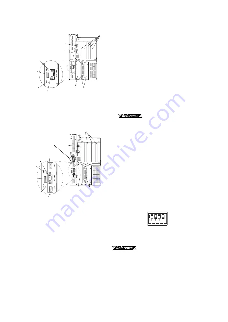
K: Keyboard Connector
A PS/2 compatible keyboard can be connected here.
L: Mouse Connector
A PS/2 compatible mouse can be connected here.
M:Expansion Slots
Slots for PCI/ISA Bus compatible expansion
boards.
N: Side Mount FDD Slot
Houses the FDD (PL-FD200) unit.
O:HDD/FDD Expansion Slot
Houses either the FFD or the HDD unit.
P: Power LED
This LED indicates both the RAS monitor
feature’s status and the PL’s power status. An
RAS alarm will cause this lamp to blink.
Appendix 2 RAS Feature
Q:Power LED Output Connector
Used when installing the PL in the optional 19”
mount to provide power LED output.
R: Hardware Reset Switch
Pushing this switch resets the PL.
S: Standard Display Connector
(GVIF OUT)
Used to connect Digital’s Standard Display
Cable. (PL-CB200-*M)
T: Standard USB Connector (USB)
This interface is USB 1.0 compliant. Compatible
USB devices can be connected here. (PL-B910/
PL-B911)
U: Dip Switches (SEL.)
Use the factory settings. (PL-B910/PL-B911 only)
Be sure to set the DU unit’s dip switches to the
same setting as the PL.
PL-X900 Series Standard Display
PL-DU6900/PL-DU7900 Users Manual.
V: Expansion Display Connector
When using 2 DU units, Digital’s display cable must
be used (PL-CB200-5M). This cable connects to the
PL’s Display Expansion Board (PL-PE200). The
picture used here shows the Display Expansion
Board installed. (PL-BP10/PL-B911 only)
PL-B900 Right Face
K
L
M
N
O
S
P
Q
U
PL-B910 Right Face
T
R
K
L
M
N
O
P
Q
R
S
Factory Settings
OFF ON OFF ON
V
Summary of Contents for PL-B900 Series
Page 12: ...12 PL B900 B910 Series Users Manual Memo...
Page 38: ...Chapter 2 Specifications 2 18 PL B900 B910 Series Users Manual Memo...
Page 62: ...Installation and Wiring 4 8 PL B900 B910 Series Users Manual Memo...
Page 80: ...System Setup 5 18 PL B900 B910 Series Users Manual Memo...
Page 84: ...PL B900 B910 Series Users Manual 6 4 Memo...
Page 88: ...7 4 PL B900 B910 Series Users Manual Memo...
Page 98: ...Appendices App 10 PL B900 B910 Series Users Manual Memo...


