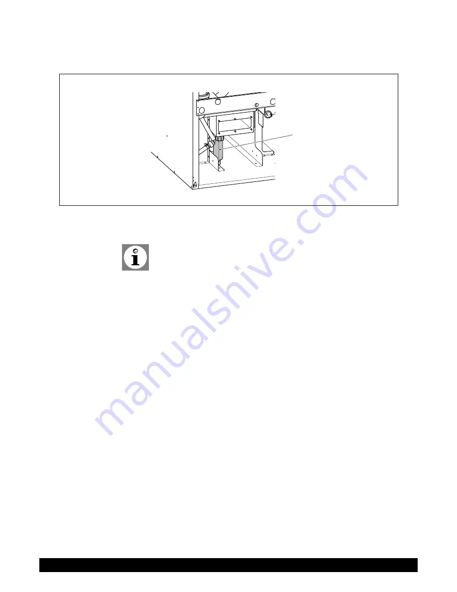
Potterton EC three 125 Installation, Operation And Maintenance Manual Download Page 138

Fig. 42: Siphon

4

C0004620

5. Remove siphon (4) and clean
6. Clean siphon
7. Reinstall siphon
8. Replace the cover of the exhaust collection pan
Note: Use a new seal when installing the cover.

9. Reinstall burner (see section 

Installing and removing burner

)

Maintenance

138

Condensing gas boiler Eurocondense three125-300 kW

7308536-02 06.13

Summary of Contents for EC three 125

Page 1: ...Working towards a cleaner future Eurocondense three Installation operation and maintenance manual To be kept by the user July 2013 heating specialists Floor Standing Condensing Gas Boilers 125 to 300kW ...

Page 2: ...ircuit water 18 4 3 1 Further information on the heating water 19 4 3 2 Diagramm Wasserhärte 19 4 4 Notes for installation location 21 4 5 Space requirement 22 4 6 Transportation 23 4 7 Application examples 24 4 8 Legend 33 5 Installation 34 5 1 Connect heating circuit 34 5 2 Condensate water connection 34 5 3 Sealing and filling of the plant 34 5 4 Flue system 34 5 5 Gas connection 35 5 6 Check t...

Page 3: ...78 8 4 2 Operator section 78 8 4 3 Radio 80 8 4 4 Time programs 80 8 4 5 Holiday programs 81 8 4 6 Heating circuits 81 8 4 7 DHW 90 8 4 8 Consumer circuit and swimming pool circuit 92 8 4 9 Swimming pool 92 8 4 10 Primary contr system pump 93 8 4 11 Boiler 93 8 4 12 Cascade 97 8 4 13 Solar 98 8 4 14 Solid fuel boiler 101 8 4 15 Buffer storage 102 8 4 16 DHW storage 104 8 4 17 Configuration 108 8 4...

Page 4: ...ing and installation locations 136 9 9 Clean burner pipe 136 9 10 Clean heat exchanger 137 9 11 Clean fan 139 9 12 Fault switch off 140 9 13 Fault code table 141 9 14 Maintenance code table 144 9 15 Operating phases of the Control Centre LMS 144 4 Condensing gas boiler Eurocondense three125 300 kW 7308536 02 06 13 ...

Page 5: ...ing spe cialist Installation Handbook Usage according to purpose Technical data circuit diagram Regulations standards CE Notes for installation location Application example Standard application Commissioning operation and programming Maintenance Heating specialist Operating Instructions Commissioning Operation User settings programming Disturbance table Cleaning maintenance Energy saving tips Cust...

Page 6: ...ion If warning is not observed danger exists for environment and the device Note tip Here you can find background information and useful tips Reference to additional information in other documents 1 4 For whom is this manual intended This installation manual is intended for the heating specialist Regarding this Manual 6 Condensing gas boiler Eurocondense three125 300 kW 7308536 02 06 13 ...

Page 7: ...n with the installation must only be carried out by a trained electrician Danger Danger to life if heating unit used improperly This device is not intended to be used by persons including children with limi ted physical sensory or mental abilitites or lack of experience and or lack of knowledge only if they are supervised by a person responsible for their safety or receive instructions on how to u...

Page 8: ...r the run off of condensate 2 4 Liquid gas under ground The EuroCondense three complies with DIN EN 126 and DIN EN 298 and therefore does not need an additional shut off valve for operation with liquid gas under ground 2 5 CE Marking The CE marking means that the gas fired fuel value devices meet the require ments of the gas devices guideline 2009 142 EG the low voltage guideline 2006 95 EG as wel...

Page 9: ...2 6 Conformity declaration EC Safety 7308536 02 06 13 Condensing gas boiler Eurocondense three125 300 kW 9 ...

Page 10: ...n 692 1389 C B A F E G Heating flow Gas 320 320 280 Supply air H I 96 122 Flange DN 65 Flange DN 65 Heating return D K N L O M Supply air optional Flue gas optional 60 61 Condensate optional 65 336 Condensate 20 40 1458 Technical Data 10 Condensing gas boiler Eurocondense three125 300 kW 7308536 02 06 13 ...

Page 11: ...ree 300 Product ID No CE 0085 CL 0072 Nominal heat input range Natural gas heating kW 20 0 125 0 28 0 170 0 35 0 215 0 42 0 260 0 48 0 300 0 LPG heating kW 35 0 125 0 35 0 170 0 48 0 215 0 58 0 260 0 58 0 300 0 Nominal heat output range Natural gas 80 60 C kW 19 2 121 6 26 8 165 8 33 5 210 1 40 2 254 5 45 9 294 0 50 30 C kW 21 3 133 1 29 8 181 3 37 4 229 6 44 9 278 1 51 4 321 3 LPG 80 60 C kW 33 5...

Page 12: ... at flue gas outlet mbar 1 0 Flue gas connection mm 160 200 Flow connection DN 65 Return connection DN 65 Connected loads International protection IP 22 Electrical connection V Hz 230 50 Max electr power consumption W 170 200 330 350 410 Max water pressure bar 6 0 Min water pressure bar 1 0 Max flow temp C 86 Hydraulic resistance T 20 K kPa 2 80 3 40 3 70 3 90 4 00 T 11 K kPa 9 00 11 00 12 10 12 7...

Page 13: ...300 E 0 50 100 150 200 250 300 350 0 5 10 15 20 25 30 35 40 3 h EC three 125 E EC three 170 E EC three 215 E EC three 260 E EC three 300 E Hydraulic resistance Water mass flow Technical Data 7308536 02 06 13 Condensing gas boiler Eurocondense three125 300 kW 13 ...

Page 14: ...3 4 Wiring Diagram Fig 3 Wiring Diagram Technical Data 14 Condensing gas boiler Eurocondense three125 300 kW 7308536 02 06 13 ...

Page 15: ... 30 823 Tab 4 Resistance values for flow sensor KVS drinking water sensor TWF return sensor KRV sensor B4 Temperature C Resistance Ω 0 32555 5 25339 10 19873 15 15699 20 12488 25 10000 30 8059 35 6535 40 5330 45 4372 50 3605 55 2989 60 2490 65 2084 70 1753 75 1481 80 1256 85 1070 90 915 95 786 100 677 Technical Data 7308536 02 06 13 Condensing gas boiler Eurocondense three125 300 kW 15 ...

Page 16: ...st connection 1 5 4 3 2 1 Remove lower rear wall 2 of the EuroCondense three 2 Remove the gas connection leading upward and make a 87 arc 1 3 Turn 87 arc 1 in the desired position side or towards the rear 4 Remove either the rear cover plate 3 or the side cover plate 4 5 Mount lower rear wall 2 6 Glue upper cover plate 5 4 1 2 Converting the supply air connection In the following picture the conve...

Page 17: ...e intake pipe elbow 3 4 Turn intake pipe elbow 3 into the side position 5 Mount lower rear wall 2 Rear supply air connection B 1 Remove lower rear wall 3 of the EuroCondense three 2 Take out cover plate 2 from lower rear wall 3 3 Remove the intake pipe leading upward with intake pipe elbow 4 Mount straight intake pipe 1 5 Mount lower rear wall 3 Before installation 7308536 02 06 13 Condensing gas ...

Page 18: ...ter hardness is greater than 17 5 degrees Clarke or 259mg litre of Calcium then this must be treated The treatment depends on the total water hardness system vol ume and the size of the boiler If in a special case a need exists to use additives in a mixture e g hardness sta bilser frost protecion agent sealing agent etc it has to be observed that the agents are compatible with each other and the p...

Page 19: ...the manufactur er If in a special case it is necessary to use additives in a mixture e g hardness stabiliser frost protection agent sealing agent etc it has to be observed that the agents are compatible with each other and the pH value is not altered Pref erably agents from the same manufacturer should be used For buffer cylinders in conjunction with solar thermal systems or solid fuel boil ers ta...

Page 20: ...er Anlage müssen bekannt sein Liegt das Volumen oberhalb der Kurve ist eine Teil Enthärtung des Leitungswassers oder ein Zusatz von Härtestabilisatoren erfor derlich Beispiel SGB 125 E Wasserhärte 14 dH 1200 l Wasservolumen s kein Zusatz erforderlich Berücksichtigt wurde ein übliches Nachfüllvolumen der Anlage Before installation 20 Condensing gas boiler Eurocondense three125 300 kW 7308536 02 06 ...

Page 21: ...ry out in spection and maintenance work Caution Danger of damaging the device Aggressive foreign substances in the combustion supply air can destroy or damage the heat exchanger Therefore the installation in rooms with high humidity see also Operation in wet rooms or heavy dust accumulation is only allowed with room air independent operating modes If the EuroCondense three is operated in rooms in ...

Page 22: ...three 125 EC three 170 EC three 215 EC three 260 EC three 300 Dimension A front 60 cm 70 cm 80 cm 90 cm 100 cm Dimension B above 50 cm Dimension C sides 50 cm Dimension D rear 10 cm Before installation 22 Condensing gas boiler Eurocondense three125 300 kW 7308536 02 06 13 ...

Page 23: ...iler to installation location manually push 2 sufficiently large steel pipes Ø 1 not included through the carrying fixture Fig 8 Pos 2 so that the boiler can be lifted and transported Danger of injury The boiler must absolutely be secured from sliding on the steel pipes For transport manually safety shoes must be worn For transport with the aid of a carrier fixture at least 4 persons are required ...

Page 24: ...7 Application examples Application example 1 EC three with one pumped circuit and DHW preparation Hydraulic plan Before installation 24 Condensing gas boiler Eurocondense three125 300 kW 7308536 02 06 13 ...

Page 25: ...Wiring plan Before installation 7308536 02 06 13 Condensing gas boiler Eurocondense three125 300 kW 25 ...

Page 26: ...Application example 2 SEC three with one mixing heating circuit and DHW preparation Hydraulic plan Before installation 26 Condensing gas boiler Eurocondense three125 300 kW 7308536 02 06 13 ...

Page 27: ...Wiring plan Before installation 7308536 02 06 13 Condensing gas boiler Eurocondense three125 300 kW 27 ...

Page 28: ...Application example 3 EC three with three mixed circuits and DHW preparation Hydraulic plan Before installation 28 Condensing gas boiler Eurocondense three125 300 kW 7308536 02 06 13 ...

Page 29: ...Wiring plan Before installation 7308536 02 06 13 Condensing gas boiler Eurocondense three125 300 kW 29 ...

Page 30: ...cation example 4 Cascade with two EC three three mixed circuits hydraulic bypass and DHW preparation Hydraulic plan Before installation 30 Condensing gas boiler Eurocondense three125 300 kW 7308536 02 06 13 ...

Page 31: ...Wiring plan right EC three Before installation 7308536 02 06 13 Condensing gas boiler Eurocondense three125 300 kW 31 ...

Page 32: ...Wiring plan left EC three Before installation 32 Condensing gas boiler Eurocondense three125 300 kW 7308536 02 06 13 ...

Page 33: ...4 8 Legend Before installation 7308536 02 06 13 Condensing gas boiler Eurocondense three125 300 kW 33 ...

Page 34: ... inserted through the opening in the rear or side wall If there is no drain underneath the condensate discharge the use of a suitable neutralisation system and pump is necessary 5 3 Sealing and filling of the plant Filling the heating plant Check tightness max water test pressure 6 bar 5 4 Flue system The Flue system must provide satisfactory control of condensation in accordance with Part J of th...

Page 35: ...ection must only be carried out by an approved heating special ist For the gas side installation and setting the factory setting data of the equip ment and optional label should be compared with the local supply conditions An approved thermally activated shut off device has to be installed In case of regionally existing old gas pipes the installation of a gas filter is recom mended Residues in pip...

Page 36: ...dense three must only be modified by an approved heating specialist To change to other type of gas only the CO2 content must be reset by adjusting the jet pressure on the gas valve see Fig 9 Moreover the following parametres of the LMS control have to be adapted see the values of the following tables Function Prog no Setting level EC three 125 EC three 170 EC three 215 Natu ral gas LPG Natu ral ga...

Page 37: ...the display has reached the basic display again 3 Press information button The message Controller stop setpoint adjust appears in the display The ac tual modulation degree will be displayed on the display 4 Press OK button The nominal value can now be changed 5 Press OK button The displayed nominal value is taken over by the control Note The regulator stop function is stopped by pressing the opera...

Page 38: ...ed Counter clockwise CO2 content is increased 4 Replace safety cap on the adjusting screw for full load 2 Set CO2 content at min output 1 EuroCondense threein the controller stop mode refer to previous section op erated at low load 2 Remove safety cap from the adjustment screw for small load 5 3 Set CO2 content on the adjustment screw for small load 5 according to Techni cal Data section with a To...

Page 39: ...pstream of the EuroCondense three It should be a double pole switch with a contact gap of min 3 mm All connected components must comply with VDE or local regulations Always apply strain relief to connecting cables 5 12 1 Cable lengths Bus sensor lines do not have mains voltage but small protective voltage They must not be installed in parallel with mains lines induced signals Shielded ca bles have...

Page 40: ...e sensor is located in the accessory bag For connection see connection diagram 5 12 6 Replacing cables All connecting cables apart from the mains cable must be replaced when necessa ry with Potterton Commercial special cables When replacing the mains cable only cables complying with BS6500 must be used 5 12 7 Protection against contact Risk of electric shock After opening the EuroCondense three th...

Page 41: ... Time and confirm 5 Finalize by pressing OK Note If the menu commissioning is interrupted by pressing ESC the menu is showing up again during the next switch on of the device 6 2 Check water pressure Caution Check before switching on if the manometers show sufficient water pressure The value has to be between 1 0 and 2 5 bar Less than 0 5 bar Top up water Caution The maximum admissable installatio...

Page 42: ...drinking water For DHW heating a setting between 50 and 60 C is recommended Note The times for DHW will be set in time programme 4 TWW For reasons of comfort the start of DHW heating should be approximately 1 hour before start of heating 6 5 Individual time programme The gas condensing boiler can be commissioned having its standard values For setting e g an individual time programme please observe...

Page 43: ...ntenance Documents The documents belonging to the boiler have to be handed over with the in structions and they have to be kept in the installation room of the boiler A copy of the commissioning sheet with confirmation and legally binding signa ture to the customer All components have been installed according to the in struction of the manufacturer The whole plant complies with the relevant Brit i...

Page 44: ...nt 2 Reset button 9 Information button 3 Reset safety temperature limiter STB 10 Rotating knob 4 Blanking plate 11 Chimney sweep button 5 Operator section ISR 12 ESC button 6 Operating mode button heating operation 13 Operation mode button DHW operation 7 Display Operation 44 Condensing gas boiler Eurocondense three125 300 kW 7308536 02 06 13 ...

Page 45: ...ormation level active 1 2 3 Reference to heating circuits PROG Setting level active Burner in operation boiler only ECO Heating system shut down auto matic summer winter changeover or automatic heating limit active 7 3 Setting up heating operation Change over between operating modes for heating operation will be carried out with the operating button Heating operation The selected setting will be m...

Page 46: ...otection operation No heating operation Temperature according to frost protection setpoint Protection functions activated Automatic summer winter switch over is not activated Automatic day heating limit is not activated DHW operation according to status 7 4 Stop drinking water operation Stop drinking water operation xxxxxxxxxxxxxx Switched on Drinking water will be prepared according to the select...

Page 47: ...ious temperatures and messages can be called up by pushing the information button Including Room and outside temperature if sensor fitted Fault or service messages Note When no faults occur and no service messages exist this information is not displayed 7 7 Error message If the fault sign appears in the display a fault exists in the heating system Press information button i Further information can...

Page 48: ...ice 3 Press OK button 4 Select parameters Manual control prog no 7140 5 Press OK button 6 Select parameter On 7 Press OK button 8 Leave programming level by pressing the operation mode button heating oper ation 7 10 Restoring factory setting The factory settings will be restored as follows 1 Press OK button 2 Select Setting level Engineer see section Programming at Programming proce dure 3 Select ...

Page 49: ...by a password Menu points Time and date Operator section Radio Time prog heating circuit 1 Time prog heating circuit 2 Time program 3 HC3 Time program 4 DHW Time program 5 Holidays heating circuit 1 Holidays heating circuit 2 Holidays heating circuit 3 Heating circuit 1 Heating circuit 2 Heating circuit 3 DHW Consumer circuit 1 Consumer circuit 2 Swimming pool circuit Primary contr system pump Boi...

Page 50: ...setting of time and date Basic display Boiler temperature Press Select with the menu point time and date Acknowledge selection with Select with the menu point hours minutes Time and date Hours minutes Acknowledge selection with Select with set the hours e g 15 hours Time and date Hours minutes Acknowledge selection with Programming 50 Condensing gas boiler Eurocondense three125 300 kW 7308536 02 0...

Page 51: ...n to the basic display Boiler temperature The previous menu point will be called up by pressing the ESC button without tak ing over previously modified values If no settings are carried out for approximate ly 8 minutes the basic display is called up without taking over previously modified values Programming 7308536 02 06 13 Condensing gas boiler Eurocondense three125 300 kW 51 ...

Page 52: ... Eu English Info Temporarily Permanently 22 E Temporarily Display of errors Code Code and text 23 E Code and text Contrast of display 25 Eu 87 Operation lock Off On 26 E Off Programming lock Off On 27 E Off Units C bar F PSI 29 Eu C bar Save basic settings No Yes This parameter is only visible in the room device 30 E No Activate basic settings No Yes This parameter is only visible if a suitable st...

Page 53: ...hange battery Delete device 131 C missing Room unit 3 Missing Ready No reception Change battery Delete device 132 C missing Outside sensor Missing Ready No reception Change battery Delete device 133 C missing Repeater Missing Ready No reception Change battery Delete device 134 C missing Operator unit 1 Missing Ready No reception Change battery Delete device 135 C missing Operator unit 2 Missing Re...

Page 54: ... 541 Eu 06 00 h min 1st phase off 542 Eu 22 00 h min 2nd phase on 543 Eu h min 2nd phase off 544 Eu h min 3rd phase on 545 Eu h min 3rd phase off 546 Eu h min Copy 555 Eu Default values No Yes 556 Eu No Time program 4 DHW Preselection Mo Su Mo Su Mo Fr Sa Su Mo Tu We Th Fr Sa Su 560 Eu Mo 1st phase on 561 Eu 05 00 h min 1st phase off 562 Eu 22 00 h min 2nd phase on 563 Eu h min 2nd phase off 564 E...

Page 55: ...educed 658 Eu Frost Protection Holidays heating circuit 3 Parameter only visible if heating circuit 3 exists Preselection Period 1 8 661 Eu Period 1 Start 662 Eu day month End 663 Eu day month Operating level Frost protection Reduced 668 Eu Frost Protection Heating circuit 1 Operating mode Heating circuit 1 Protection Automatic Reduced Comfort 700 Eu Automatic Comfort setpoint 710 Eu 20 0 C Reduce...

Page 56: ...ing Functional heating Manually 850 C Off Floor curing setp manually 851 E 25 C Floor curing setp current 855 E C Floor curing day current 856 E 0 C Excess heat draw Off Heating mode Always 861 E Heating mode With buffer storage tank Off Heating mode Always 870 E Yes With prim contr system pump No Yes 872 E Yes Pump speed reduction Operating level Characteristic 880 E Characteristic Pump speed min...

Page 57: ...imum stop control max 1091 E 0 min Reduced setp increase start 1100 E C Reduced setp increase end 1101 E 15 C Continuous pump operation No Yes 1109 E No Overtemp prot pump circuit Off On 1120 E Off Mixing valve boost 1130 E 5 C Actuator running time 1134 E 120 s Floor curing function Off Functional heating Curing heating Functional curing heating Curing Functional heating Manually 1150 E Off Floor...

Page 58: ...E 8 C Flow temp setpoint max 1341 E 80 C Flow temp setpoint room stat 1342 E C Delay heat request 1346 E 0s Room influence 1350 C Room temp limitation 1360 E 0 5 C Boost heating 1370 E C Quick setback Off Down to reduced setpoint Down to frost prot setpoint 1380 E Down to reduced set point Optimum start control max 1390 E 0 min Optimum stop control max 1391 E 0 min Reduced setp increase start 1400...

Page 59: ... program 4 DHW Charging priority Absolute Shifting None MC shifting PC absolute 1630 E MC shifting PC absolute Legionella function Off Periodically Fixed weekday 1640 E Fixed weekday Legionella funct periodically 1641 E 3 Legionella funct weekday Monday Tuesday Wednesday Thursday Friday Saturday Sun day 1642 E Sunday Legionella funct time 1644 E Legionella funct setpoint 1645 E 65 C Legionella fun...

Page 60: ...No Yes 1978 E Yes With prim contr system pump No Yes 1980 E Yes Swimming pool Setpoint solar heating 2055 Eu 26 C Setpoint source heating 2056 Eu 22 C Charging priority solar Priority 1 Priority 2 Priority 3 2065 E Priority 3 Swimming pool temp max 2070 E 32 C With solar integration No Yes 2080 E Yes Primary contr system pump Flow temp setpoint min 2110 E 8 C Flow temp setpoint max 2111 E 80 C Sys...

Page 61: ...Heating and DHW mode 2305 E Heating and DHW mode Temp differential max 2316 C 45 C Temp differential nominal 2317 C 15 C Pump modulation None Demand Boiler setpoint Temp differential nominal Burner output 2320 E Temp differential nomi nal Pump speed min 2322 E 10 Pump speed max 2323 E 100 Output nominal 2330 E EC three 125 125 kW EC three 170 170 kW EC three 215 215 kW EC three 260 260 kW EC three...

Page 62: ...iff off max HCs 2456 E 5 C Switching diff on DHW 2460 E 4 C Switching diff off min DHW 2461 E 5 C Switching diff off max DHW 2462 E 7 C Delay heat req special op 2470 E 0 s Pressure switch shutdown Start prevention Lockout position 2500 E Start prevention Cascade Lead strategy Late on early off Late on late off Early on late off 3510 E Late on late off Release integral source seq 3530 E 50 C min R...

Page 63: ...00 h min Collector start funct grad 3834 E min C Collector frost protection 3840 E C Collector overtemp prot 3850 E C Evaporation heat carrier 3860 E 130 C Antifreeze None Ethylene glycol Propylene glycol Ethyl and propyl glycol 3880 E Propylene glycol Antifreeze concentration 3881 E 50 Pump capacity 3884 E 200 l h Pulse valency 3887 E 10 l Solid fuel boiler Locks other heat sources Off On 4102 E ...

Page 64: ...rward time 5011 E 01 00 min Flow setpoint boost 5020 E 18 C Transfer boost 5021 E 10 C Type of charging Recharging Full charging Full charging legio Full charg 1st time day Full charg 1st time legio Charging 5022 E Full charging Switching diff 5024 E 4 C Charging time limitation 5030 E 120 min Discharging protection Off Always Automatically 5040 E Automatic Charging temp max 5050 E 65 C Re cooling...

Page 65: ...B36 No Yes 5146 E Yes Min start temp diff Q33 5148 E 3 C Excess interm circ temp del 5151 E 30 s Configuration Heating circuit 1 Off On 5710 C On Heating circuit 2 Off On 5715 C Off Heating circuit 3 Off On 5721 C Off DHW sensor DHW sensor B3 Thermostat 5730 E DHW sensor B3 DHW controlling element Q3 No charging request Charging pump Diverting valve 5731 E Charging pump Basic pos DHW div valve Las...

Page 66: ...r sensor B4 Buffer sensor B41 Common flow sensor B10 Solid fuel boiler sensor B22 DHW charging sensor B36 Buffer sensor B42 Common return sensor B73 Cascade return sensor B70 Swim ming pool sensor B13 Solar flow sensor B63 Solar return sensor B64 5930 C Collector sensor B6 Sensor input BX2 Parameters see Sensor input BX1 prog no 5930 5931 C DHW sensor B31 Sensor input BX3 Parameters see Sensor inp...

Page 67: ...ar Operating level DHW Operating level HC1 Operat ing level HC2 Operating level HC3 Room thermostat HC1 Room thermostat HC2 Room thermostat HC3 DHW thermostat Pulse count Checkb sign flue gas damper Start prevention 5977 C None Contact type H5 NC NO 5978 C NO Function extension module 1 None Multifunctional Heating circuit 1 Heating circuit 2 Heating circuit 3 Solar DHW Primary contr system pump 6...

Page 68: ...onsumer request VK3 Excess heat discharge Release swi pool solar Operating level DHW Operating level HC1 Operat ing level HC2 Operating level HC3 Room thermostat HC1 Room thermostat HC2 Room thermostat HC3 Limit thermostat HC Start prevention Consumer request VK1 10V Consumer request VK2 10V Consumer request VK3 10V Preselected output 10V 6046 C None Contact type H2 module 1 NC NO 6047 C NO Voltag...

Page 69: ... E Check no storage tank 6215 E Check no heating circuits 6217 E Software version 6220 E LPB system Device address 6600 C 1 Bus power supply function Off Automatic 6604 E Automatic Bus power supply state Off On 6605 E Display system messages No Yes 6610 E Yes Alarm delay 6612 E min Action changeover functions Segment System 6620 E System Summer changeover Locally Centrally 6621 E Locally Optg mode...

Page 70: ...0 E SW diagnostic code 2 Burner control phase 2 6815 E History 3 Date Time Error code 6820 E SW diagnostic code 3 Burner control phase 3 6825 E History 20 Date Time Error code 20 6990 E SW diagnostic code 20 Burner control phase 20 6995 E Service special operation Burner hours interval 7040 E h Burn hrs since maintenance 7041 E 0 h Burner start interval 7042 E Burn starts since maint 7043 E 0 Main...

Page 71: ...lay output QX2 Relay output QX3 Relay output QX21 module 1 Relay output QX22 mod ule 1 Relay output QX23 module 1 Relay output QX21 module 2 Relay output QX22 module 2 Relay output QX23 module 2 Relay output QX21 module 3 Relay output QX22 module 3 Relay output QX23 module 3 7700 C No test Output test P1 7713 C PWM output P1 7714 C Outside temp B9 7730 C DHW temp B3 B38 7750 C Boiler temp B2 7760 ...

Page 72: ...meter not intended for operation with WGS Priority state source 1 Missing Faulty Manual control active Heat generation lock active Chimney sweep funct active Temporarily unavailable Outside temp limit active Not released Released 8100 C Priority state source 2 Parameters see Priority state source 1 prog no 8100 8102 C Priority state source 3 Parameters see Priority state source 1 prog no 8100 8104...

Page 73: ...rity state source 1 prog no 8100 8128 C Priority state source 16 Parameters see Priority state source 1 prog no 8100 8130 C Cascade flow temp 8138 C Cascade flow temp setp 8139 C Cascade return temp 8140 C Cascade return temp setp 8141 C Source seq ch over current 8150 C Diagnostics heat generation Boiler pump Q1 8304 E Boiler pump speed 8308 E Boiler temp 8310 C Boiler temperature setpoint 8311 C...

Page 74: ...lect overtemp 8531 E Hours run Collector pump 8532 Eu Solid fuel boiler temp 8560 C Hours run solid fuel boiler 8570 C Diagnostics consumers Outside temperature 8700 Eu Outside temperature minimum 8701 Eu Outside temperature maximum 8702 Eu Outside temp attenuated 8703 E Outside temp composite 8704 E Heating circuit pump 1 Off On 8730 C Heat circ mix valve 1 open Off On 8731 C Heat circ mix valve ...

Page 75: ...9 C DHW pump Off On 8820 C Speed DHW pump 8825 E Speed DHW interm circ pump 8826 E DHW temp 1 8830 C DHW temp setpoint C DHW temp actual value bottom B31 8832 C DHW circulation temp 8835 E DHW charging temp 8836 E Flow temp setpnt consumer circuit 1 8875 C Flow temp setpnt consumer circuit 2 8885 C Flow temp setpnt swimming pool 8895 C Swimming pool temp 8900 C Swimming pool setpoint 8901 C Primar...

Page 76: ...23 module 3 Off On 9058 C Burner control Prepurge time 9500 F 20 s Nominal output prepurging 9504 F EC three 125 59 3 kW EC three 170 75 5 kW EC three 215 77 1 kW EC three 260 97 7 kW EC three 300 103 9 kW Nominal output ignition load 9512 F EC three 125 59 3 kW EC three 170 75 5 kW EC three 215 77 1 kW EC three 260 97 7 kW EC three 300 103 9 kW Nominal output Partial load 9524 F EC three 125 20 k...

Page 77: ...control Floor curing setp current Floor curing day current Room temperature Room temperature min Room temperature max Cascade flow temp Controller stop setpoint Boiler temp Outside temp Outside temp min Outside temp max DHW temp 1 DHW consumption temp Collector temp 1 24 hour yield solar energy Solid fuel boiler temp Buffer temp 1 Swimming pool temp State heating circuit 1 State heating circuit 2 ...

Page 78: ...he set date 8 4 2 Operator section Language 20 The language of the menu guidance can be modified under prog no 20 Info 22 Temporarily The information display returns to the basic display after 8 minutes Permanently The information display remains permanently displayed after call up with the information button Contrast of display 25 Under prog no 25 the contrast of the display can be adjusted Opera...

Page 79: ... the pure operation without room functions and is not needed in connection with this controller service unit this setting is used for example to secure or save control settings Room controller 1 assign ment 42 If setting Room controller 1 prog no 40 was selected at the room controller de termine the heating circuits to which room controller 1 is assigned under prog no 42 Operation HC2 HC3 P 44 46 ...

Page 80: ...ram 5 is not assigned a function and can be freely used for any applica tion using an output QX Preselection 500 520 540 560 600 Selection of weekday or day blocks The day blocks Mo Su Mo Fr and Sa Su as sist the adjustment The set times are only copied to the individual weekdays and can be changed in the individual day settings as required The times of the individual weekdays always determine the...

Page 81: ...50 1050 1350 this value is used for calculation of the flow temperature to theoretically reach the set room tempera ture Reduced setpoint 712 1012 1312 Setting of the desired room temperature during the reduced heating phase With out room sensor or with the room influence prog no 750 1050 1350 this value is used for calculation of the flow temperature to theoretically reach the set room temperatur...

Page 82: ...oom temperature Heating curve adaption 726 1026 1326 Automatic adaptation of the heating nominal line to the actual circumstances due to which a correction of the heating nominal line gradient becomes obsolete For automatic adaptation of the heating curve a room sensor must be connected The value for room influence see prog no 750 1050 1350 must be set between 1 and 99 Should there be radiator val...

Page 83: ... the re quired flow temperature setpoint of the heating circuit reaches the respective limit value this remains constantly on maximum or minimum value during con tinuously increasing or decreasing heat requirement Flow temp setpoint room stat 742 1042 1342 For room thermostat mode the flow setpoint set here applies Setting C gives the flow temperature setpoint from the outside temperature and the ...

Page 84: ... set and the room tempera ture is taken into consideration even more Caution Open radiator valves Should there be radiator valves in the leading room assembly location of the room sensor these have to be fully opened Setting for weather compensation with room influence 1 99 Setting for pure weather compensation Setting for pure room compensation 100 Room temp limitation 760 1060 1360 The heating c...

Page 85: ... quick setback the heating circuit pump is turned off and the mixing valve is also closed during mixing circuits During the quick setback no heat re quirement is sent to the heat generator The quick setback is possible with or without room sensor with room sensor the heating circle function is switched off as long as the room temperature has drop ped to the reduced setpoint or frost protection set...

Page 86: ...t the conversion of the operating level compared to the programmed time point is moved forward so that the building dynamics heat up and cool down time is considered In this way the de sired temperature level is reached exactly at the programmed time point If this is not the case too early or too late a new switching time point is calculated which is used the next time Without room sensor an advan...

Page 87: ...the heating circuit pump boiler pump can be switched off by quick setback or reaching the room set point Yes the heating circuit pump boiler pump remains switched on even during the quick setback and after reaching the room set point Overtemp prot pump circuit 820 1120 1420 This function prevents overheating of the pumped heating circuit by switching on and switching off the pump if the flow tempe...

Page 88: ...ional heating Ch Curing heating Important The respective regulations and standards of the screed manufacturer have to be observed A correct function is only possible with a correctly installed plant hydraulic elec trical systems and settings Deviations can only lead to damage of the screed The floor curing function can be stopped prematurely by setting 0 OFF Floor curing setp manually 851 1151 145...

Page 89: ...e speed of the heating circuit pump is calcula ted acc to the operating level The pump is controlled in operating level comfort incl optimization or during active floor curing function with parameterized maximum speed With reduced operating level the pump is controlled with the parameterized minimum speed Characteristic The pump speed of the heating circuit pump is calculated based on the actually...

Page 90: ...ly controlled to the nominal drinking water temperature value independent from the time switching pro grammes Time programs HCs The DHW temperature will be switched over between the nominal DHW temperature value and the reduced nominal DHW temperature value depending on the time switching programs Every time the switching on time will be moved forward In case of several releases per day it is move...

Page 91: ... 1642 Legionella funct periodically 1641 Setting the interval for the legionella function periodically recommended setting in case of additional drinking water heating by solar plant in connection with a st tankmixing pump Legionella funct weekday 1642 Selection of the weekday for the legionella function fixed weekday factory set ting Legionella funct time 1644 Setting the start time for the legio...

Page 92: ...d into which operating mode is switched into None the function is switched off 8 4 8 Consumer circuit and swimming pool circuit Flow temp setp cons request 1859 1909 1959 Setting of the flow setpoint is done with this function which is effective during active request of the consumer circuit DHW charging priority 1874 1924 1974 Setting if the connected consumerscircuit pump should be used with prio...

Page 93: ...gher as the requested setpoint of the mixer flow temperature since these cannot otherwise be corrected The controller from the boiler temperature setpoint from the boost set here and the current flow temperature setpoint Actuator running time 2134 Setting the actuator running time of the used mixing valve Prim contr system pump 2150 Before buffer storage tank the primary controller feed pump is ar...

Page 94: ...lock 2301 Stop of boiler pump in case of activated manual heat generation lock e g via H1 Off Switching off not activated On Switching off activated Impact heat generation lock 2305 With these parameter it can be set whether the heat generation lock should be effective only for heating requests or also for DHW requests Heating mode only Only the heating request is locked DHW requests will con tinu...

Page 95: ... the working range can be defined in percent of output The control translates the percent data internally into speeds The value 0 corresponds to the minimum pump speed Pump speed max 2323 The pump speed and with it the power consumption can be limited via the maxi mum value Output nominal 2330 Output basic stage 2331 The settings under prog no 2330 and prog no 2331 are necessary when setting up bo...

Page 96: ...not active Fan shutdown delay 2446 If no heating requirement exists the voltage supply of the fan is switched off The time is set here in which the fan gets voltage anyway Controller delay 2450 The controller delay is used for a stabilisation of the combustion conditions espe cially after a cold start After release of the firing automation by the controller this remains on the set output for a spe...

Page 97: ...ioning on the burner control and the actuation of the pumps With open pressure switch is a start prevention or lockout position triggered The pump actuation is also locked for protection against dry running If the water pressure increases again and the switch closes again with a start prevention these are automatically again cancelled and the pump actuation is again re leased 8 4 12 Cascade Lead s...

Page 98: ...0 has elapsed Last the last boiler in the addressing always remains as the last boiler for all other boilers the boiler sequence is changed after the time set in prog no 3540 has elapsed Leading source 3544 The setting of the leading source is only used in combination with the fixed se quence of the source sequence prog no 3540 The generator defined as the leading generator is always put into oper...

Page 99: ...mp diff ON buffer 3813 Temp diff OFF buffer 3814 Charging temp min buffer 3815 The switching on and switching off point of the collector pump is set with these functions Basis is the temperature difference between collector temperature and storage temperature of the buffer In addition to the temperature difference reaching a certain minimum collector temperature is necessary for the buffer storage...

Page 100: ... A 1610 Nominal setpoint Buffer setpoint drag pointer B 5050 DHW Charging temp max 4750 Buffer storage tank charging temp max C DHW storage tank temp max set by factory 90 C Buffer storage temperature max set by factory 90 C Charging time relative prio 3825 If the preferred storage tank corresponding to the charging control not be charg ed during the time set here the priority goes to the next sto...

Page 101: ...verheating of the collector pump in case of evaporating danger of the heat carrying medium due to high collector tempera ture Antifreeze 3880 Information of the antifreeze used Antifreeze concentration 3881 Input of antifreeze concentration for usage measurement of solar energy Pump capacity 3884 Input of the flow of the installed pump for calculation of the brought in volume for usage measurement...

Page 102: ...5 Buffer storage Auto generation lock 4720 The hydraulic separation of heat source and buffer storage tanks achieved by the automatic heat generation lock The heating source will only be started if the buf fer storage tank cannot cover the actual heat request The following settings are possible None the automatic heat generation lock is de activated With B4 the automatic heat generation lock will ...

Page 103: ... return is re routed to the lower buf fer storage tank part The function can either be used as return temperature in crease or as return temperature decrease The way this works is defined in prog no 4796 Using the definition of the temperature differences in prog no 4790 and 4791 the switch on and switch off point of the return redirection is established In prog no 4795 the buffer storage tank sen...

Page 104: ... for the full charging function the function is ended Full charging temp min 4811 The buffer storage tank is charged minimally to the set value Full charging sensor 4813 With B4 For the full charging function the buffer storage tank sensor B4 is consid ered With B42 B41 For the full charging function the buffer storage tank sensor B42 if not available buffer storage tank sensor B41 is considered 8...

Page 105: ...er depending on the selected charging priority prog no 1630 and the hydraulic switch has too little or no power Of ten it is therefore practical to restrict the time of DHW charging Discharging protection 5040 The function ensures that the DHW pump Q3 first switches on if the temperate in the heat generator is sufficiently high Application with sensor The charging pump is first switched on if the ...

Page 106: ... temperature will be achieved with an external ther mostat with setpoint control of the controller Automatic Push 5070 The DHW Push can activated by hand or automatically It causes a one time DHW charging to the nominal setpoint Off The DHW Push can only activated by hand On If the DHW temperature drops by more than two switching differences prog no 5024 below the reduced setpoint prog no 1612 one...

Page 107: ... the end criterion of a full charging during control is specified on the charging sensor B36 If the contents of the layer storage is charge to the bottom the temperature increases on the charging sensor Flow setp compensation de lay 5142 The filter time for the setpoint lead is set here Flow setp compensation Xp 5143 The P band Xp defines the amplification of the controller A smaller Xp value lead...

Page 108: ...rature Thermostat Control of domestic hot water temperature as a function of the switching status of a thermostat connected to DHW sensor B3 Note When using a DHW thermostat no reduced mode is possible This means if reduced mode is active the DHW preparation is blocked with the thermostat Caution No frost protection for DHW The domestic water frost protection cannot be guaranteed Sensor B38 An ins...

Page 109: ...cuit 1 and DHW and switches between DHW mode and heat circuit 1 mode All other requests are not connected hydraulically via the diverting valve DV and the boiler pump but rather directly connected to the boiler Solar controlling element 5840 The solar heating system can also be operated with charging pumps instead of with a collector pump and diverting valves for the storage tank connection Charge...

Page 110: ...ase or the buffer storage tank partial charging Solar pump ext exch K9 here the solar pump external exchanger K9 must have been set for the external heat exchange Solar ctrl elem buffer K8 if several exchangers are connected the buffer storage must be set at the respective relay output and the type of solar regulating unit must be defined under prog no 5840 Solar ctrl elem buffer K8 if several exc...

Page 111: ...return sensor B73 Return sensor for the function return diversion Cascade return sensor B70 common return sensor for boiler cascades Swimming pool sensor B13 Sensor for measurement of swimming pool temp Solar flow sensor B63 this sensor is required for the solar usage measurement Solar return sensor B64 this sensor is required for the solar usage measure ment Function inputs H1 H4 H5 5950 5970 597...

Page 112: ...uest VKx 10V The application nodes external load x receives a volt age signal DC 0 10 V as heat request The linear curve is defined via two fix points voltage value 1 function value 1 and voltage value 2 function value 2 only applies to H1 Preselected output The source receives a voltage signal DC 0 10 V as output request The linear curve is defined via two fix points voltage value 1 function valu...

Page 113: ...eed pump For this use the respective settings can be adjus ted in the menu point Primary controller feed pump Relay output QX21 QX23 6030 6038 Relay outputs for the moduls 1 2 and 3 Explanations see prog no 5890 Sensor input BX21 BX22 6040 6045 Sensor input for the moduls 1 2 and 3 Functions in addition to the basic functions will be possible by configuring the sensor inputs BX21 and BX22 Explanat...

Page 114: ...exch K9 if several exchangers are connected the buffer storage must be set at the respective relay output and the type of the solar regulating unit must be defined in prog no 5840 Solar pump swi pool K18 if several exchangers are connected the the swim ming pool must be set at the respective relay output and the type of the solar regulating unit must be defined in prog no 5840 Sensor type collecto...

Page 115: ...his happens au tomatically however after changing the plant removal of a sensor the state at the sensor terminals must be stored new Control numbers generator 1 storage heating circuit 6212 6213 6215 6217 The basic device generates a control number for identification of the plant scheme which is composed of the numbers listed in Tab 7 Page 115 Tab 7 Check no heat source 1 prog no 6212 Solar A coll...

Page 116: ...out ex changer 23 Charging pump intermediate circuit 1 exchanger 25 Diverting valve intermediate circuit without ex changer 26 Diverting valve intermediate circuit 1 exchanger 28 Primary control intermediate circuit without ex changer 29 Primary control intermediate circuit 1 exchanger Tab 9 Check no heating circuit prog no 6217 Heating circuit 3 Heating circuit 2 Heating circuit 1 0 No heating ci...

Page 117: ...ommunication errors However it must be realised that briefly occurring malfunctions which continue and quickly occur again are also filtered out with this Display systemmessages 6610 If the setting Central is activated under progr no 6221 and 6223 the action for this setting can be set The following settings are possible Segment the changeover is done for all controllers in the same segment System...

Page 118: ...he controller is then continually adapted to the system time Master The time of day can be modified at the control The time of the control ler is the default for the system The system time is adapted Outside temp source 6650 In the LPB system only one single outside temperature sensor is necessary This delivers the signal via the LPB to the controller without sensor In the display the segment numb...

Page 119: ...of the burner ionisation current service alarm The service alarm can only be reset if the reason for service is taken care of Chimney sweep function 7130 The chimney sweep function is switched on or off under this prog no Note The function is switched off by the setting Off or automatically if the maximum boiler temperature is reached It can also be directly activated via the chimney sweep button ...

Page 120: ...ust be unlocked after ending the transmission Error 183 parameterization is displayed Writing on stick Starts writing the data from the LMS control to the stick This operation is only possible with WRITE sticks The data is written in the previous ly set data set Before writing of the data begins it is checked whether the data fits on the stick and the respective customer number is correct The text...

Page 121: ...icted buffer Forced draw Forced draw DHW Forced draw source Overrun active Comfort heating mode Opt start ctrl boost heating Optimum start control Boost heating Comfort heating mode Reduced heating mode Optimum stop control Reduced heating mode Frost protection active Frost prot room active Frost protection flow active Frost prot plant active Summer operation Summer operation Off 24 hour Eco activ...

Page 122: ... legionella setp Forced nominal setp Charg el imm heater El charging legionella setp El charging nominal setp El charging reduced setp El charging frost prot setp El imm heater released Push active Push legionella setp Push nominal setp Charging active Charging legionella setp Charging nominal setp Charging reduced setp Frost protection active Frost protection active Frost protection Instantaneous...

Page 123: ...Min limitation part load Min limitation active In operation Protective start Protective start part load Return limitation Return limitation part load Charging buffer Charging buffer In op for HC DHW In op for HC DHW In part load op for HC DHW In part load op for HC DHW Released for HC DHW Released for HC DHW In operation for DHW In operation for DHW In part load op for DHW In part load op for DHW ...

Page 124: ...active Overtemp prot active Max charging temp reached Max charging temp reached Charging DHW buffer swi pool Charging DHW buffer swi pool Charging DHW buffer Charging DHW buffer Charging DHW swi pool Charging DHW swi pool Charging buffer swi pool Charging buffer swi pool Charging DHW Charging DHW Charging buffer Charging buffer Charging swimming pool Charging swimming pool Radiation insufficient M...

Page 125: ...DHW In operation for DHW In part load op for DHW In part load op for DHW In op for HC DHW In op for HC DHW In part load op for HC DHW In part load op for HC DHW Overrun active Overrun active In operation In operation Assisted firing active Assisted firing active Released Released Frost protection active Frost prot plant active Boiler frost prot active Off Off The following messages are possible un...

Page 126: ...red temp Charged min charging temp Cold Cold No request No request The following messages are possible under swimming pool End user E Commissioning Technician menu State Manual control active Manual control active Fault Fault Heating mode restricted Heating mode source Heated max Swimming pool temp Heated max Swimming pool temp Heated Heated Setpoint solar Heated Setpoint source Heating mode Heati...

Page 127: ...venting time Note This parameter must only be changed by a heating specialist Fan output speed slope 9626 Fan output speed Y section 9627 With this parameter the rotational speed of the fan can be adjusted e g for com plex exhaust systems or the conversion of gas condensing boilers for operating with liquid gas Prog no 9626 equates to the incline of the fan characteristic curve Prog no 9627 equate...

Page 128: ...er areas and heating surfaces Replace wear parts see Spare parts list Caution Only original spare parts must be used Check connection and seal locations of water filled parts Check safety valves for correct function Check operating pressure and possibly fill in water De aerate heating plant De aerate heating plant and return gravity lock into operating position End control and documentation of per...

Page 129: ...turi tube Gas valve Heating return Heating flow Gas connection Flue gas connection Safety group connection Supply air connection Heat exchanger Silencer Ignition transformer below the control unit Syphon Servicing cover Pressure switch below the control unit Maintenance 7308536 02 06 13 Condensing gas boiler Eurocondense three125 300 kW 129 ...

Page 130: ...rol unit Syphon Servicing cover Pressure switch below the control unit 9 3 Disassembling and installing burner Risk of electric shock Before performing service work power to the boiler must be shut off and it must be secured from accidentally being switched back on Disassembling burner 1 Close gas shut off device 2 Remove front panel of the SGB E gas condensing boiler 3 Release ignition cable ioni...

Page 131: ...screws on the flange of the venturi tube 2 and loosen the venturi tube with seal in the flange from the exhaust silencer 1 Fig 33 Release gas connection hose on the gas valve 3 4 C0004595 6 Release gas connection hose 3 on the gas valve 4 Maintenance 7308536 02 06 13 Condensing gas boiler Eurocondense three125 300 kW 131 ...

Page 132: ...uts and washers and pull out the entire burner 5 with burner seal 6 forwards Installing burner The installation of the burner is done in the opposite sequence Note Use new seals when installing the burner Maintenance 132 Condensing gas boiler Eurocondense three125 300 kW 7308536 02 06 13 ...

Page 133: ...ed Observe the spare part instructions Note After installation of the burner the burner pipe lies on the rear combustion room insulation 9 5 Installing the combustion room insulation The burner must be removed to install or replace the combustion room insulation 1 Remove the existing combustion room insulation 1 from the rear wall of the heat exchanger see Fig 35 2 Remove the residue of the insula...

Page 134: ...om accidentally being switched back on Fig 36 Remove ignition electrode block Eurocondense three 215 300 Eurocondense three 125 170 1 2 C0004597 2 1 1 Loosen ignition cable 2 Remove nuts and pull out the ignition electrode block 1 with the seal 2 3 Insert the new ignition electrode block with seal and fasten with nuts Note Installation position and electrode clearance has to be maintained accordin...

Page 135: ...s during the ignition process Changing the ionisation electrode Danger of electric shock Before performing service work power to the boiler must be shut off and it must be secured from accidentally being switched back on Fig 37 Removing ionisation electrode 1 2 Eurocondense three 215 300 Eurocondense three 125 170 1 2 1 Release ionisation line 2 Remove nuts and pull out the ionisation electrode 1 ...

Page 136: ...ng and removing burner Fig 39 Dismantle burner pipe C0004611 1 2 2 Remove screws and remove burner pipe 1 with the burner pipe seal 2 3 Clean the burner pipe with compressed air 4 Reinstall burner pipe with burner pipe seal Note Use a new burner pipe seal when installing the burner pipe 5 Reinstall burner see section Installing and removing burner Maintenance 136 Condensing gas boiler Eurocondense...

Page 137: ...llection pan 1 2 C0004618 2 Remove screws and remove cover 1 of the exhaust collection pan with seal 2 Fig 41 Heat exchanger 3 C0004619 3 Clean heat exchanger 3 with a brush or rinse with water 4 Remove deposits from the exhaust collection pan Maintenance 7308536 02 06 13 Condensing gas boiler Eurocondense three125 300 kW 137 ...

Page 138: ...phon 7 Reinstall siphon 8 Replace the cover of the exhaust collection pan Note Use a new seal when installing the cover 9 Reinstall burner see section Installing and removing burner Maintenance 138 Condensing gas boiler Eurocondense three125 300 kW 7308536 02 06 13 ...

Page 139: ... seal 2 from burner cover 1 3 Remove screws and release venturi pipe incl gas valve 5 with seal 4 from fan 4 Clean fan with compressed air 5 Reassemble burner in the opposite sequence Note Use new seals when reassembling the burner 6 Reinstall burner see section Installing and removing burner Maintenance 7308536 02 06 13 Condensing gas boiler Eurocondense three125 300 kW 139 ...

Page 140: ...on theoperating panel points out the cause of the disturbance see fault code table Burner does not start No voltage at the control and regulating centre no burner ON signal from the heating circuit control see fault code table Burner goes into disturbance status Without flame formation No ignition ionisation electrode has ground connection no gas In spite of flame formation the burner goes on faul...

Page 141: ...m heating specialist1 54 Flow temperature DHW sensor fault 57 Drinking water circulation temperature sensor fault 60 Room temperature 1 sensor fault 65 Room temperature 2 sensor fault 68 Room temperature 3 sensor fault 70 Storage tank temp 1 top sensor fault 71 Storage tank temp 2 bottom sensor fault 72 Storage tank temp 3 middle sensor fault 73 Collector temperature 1 sensor fault 81 LPB short ci...

Page 142: ...ct heating specialist lack of gas polarity of mains connection safe ty period check ignition electrode and ionisation current 1 3 146 Configuration fault Common message 151 Internal fault Check parameter see Adjustment Table Heating Expert and or Call up Values reset LMS change LMS heating expert 1 3 152 Parameterization fault 160 Fan fault Fan possible defective speed threshold set wrongly 3 162 ...

Page 143: ...r 352 Pr less header addr err 353 Common flow sensor B10 missing 371 Flow temperature 3 Heating circuit 3 monitor ing 372 Limit thermostat HC3 373 Expansion module 3 fault collective fault 378 Repetition counter internal fault expired 382 Repetition counter fan fault expired 384 Extran light 385 Ned undervoltage 386 Fan revolutions per minute has left valid range 387 Air pressure switch fault 426 ...

Page 144: ...d start of safety time for flame formation ioni sation current build up tsa1 Safety time constant Flame monitoring with ignition tsa2 Safety time variable Flame monitoring without ignition it Interval time Flame stabilisation MOD Modulating mode Burner in operation THL2 Subsequent ventilation with last operating fan speed Fan continues to run THL2A Subsequent ventilation with pre purging fan speed...

Page 145: ...isassembling Burner 130 Discharge from safety valve 43 E ECO 45 Emergency operation 48 Error message 47 F Factory setting 79 Factory settings 35 Fault 140 Fault code table 141 Fault message 45 Floor curing function 88 Flue lenghts 34 Flue system 34 Frost protection plant 115 115 Frost protection setpoint 46 81 Fuses 40 G Gas connection 35 Gas filter 35 Gravity lock 128 H Heating curve Adaptation 8...

Page 146: ...ues 15 Restoring factory setting 48 Room influence 84 Room temperature 42 Comfort setpoint 46 Reduced setpoint 47 S Safety valve 34 128 Service message 45 Set frost protection temperature 45 Shut off valve 35 Software version 80 116 Spare parts 128 Standards 8 State 120 Strain reliefs 39 Summer winter heating limit 82 T Technical Data 11 Time program 42 Topping up water 128 U Used symbols 6 Uso ap...

Page 147: ...Space for notes 7308536 02 06 13 Condensing gas boiler Eurocondense three125 300 kW 147 ...

Page 148: ... 0713 Baxi Commercial Wood Lane Erdington Birmingham B24 9QP Email potterton commercial baxicommercialdivision com www pottertoncommercial co uk heating specialists Sales 0845 070 1056 Technical 0845 070 1057 RS 33961 ...

Reviews: