32
DMC Repair Manual
Parts Replacement
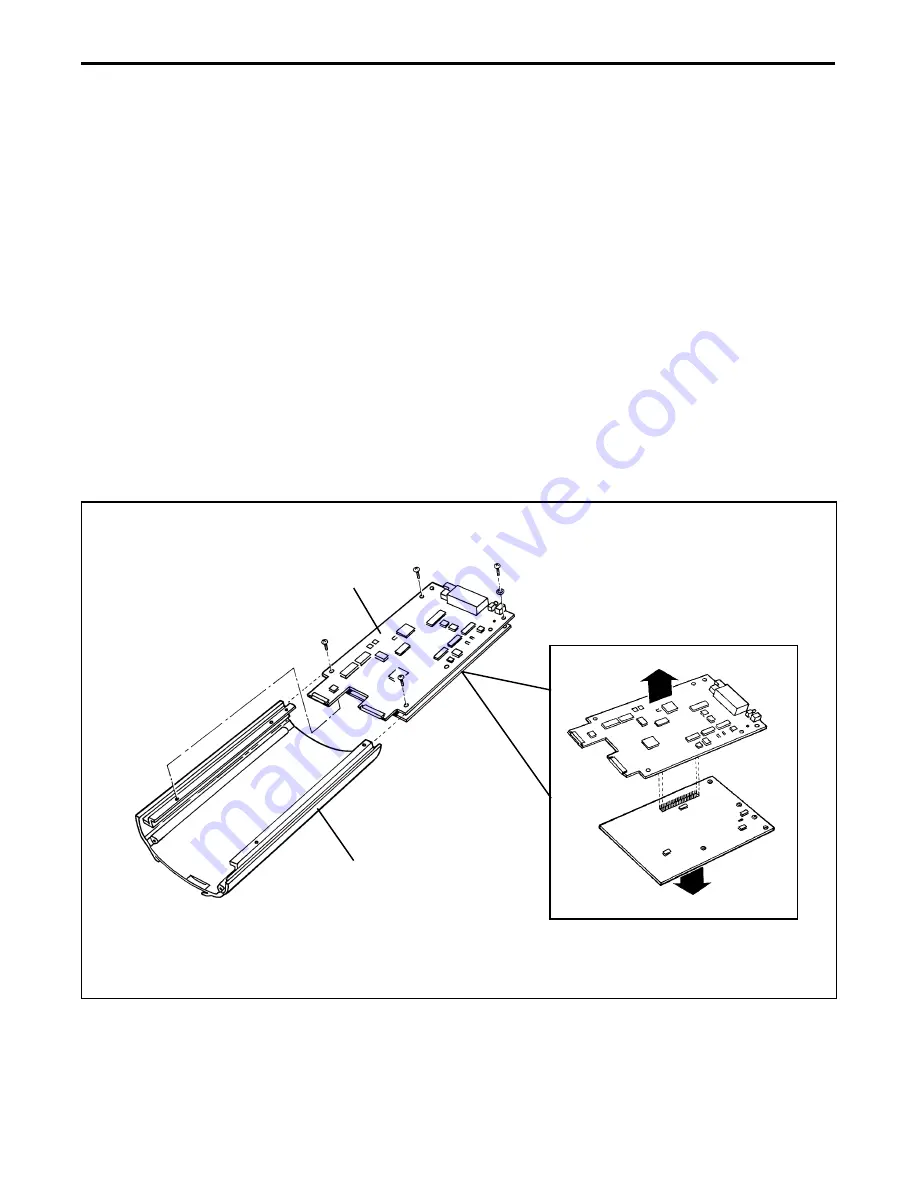
Electronics Assembly (Front End/Back End Boards) (Figure 2-9)
Removal
1. Remove the bottom extrusion.
2. Remove the front panel and optics assembly.
3. Remove the four (4) screws and star washers that secures the electronics assembly to
the top extrusion supports:
4. Slide out the electronics assembly from the top extrusion.
5. Remove the rear panel and XSYNC assembly.
6. Disconnect the back end board (male connector J3) to the front end board (female
connector J3).
Figure 2-9. Removing electronic assembly (back/front end boards)
Top Extrusion
Electronics
Assembly
Back End
Board
Front End
Board
J3
Summary of Contents for Digital Microscope Camera
Page 5: ...1 Camera Overview...
Page 13: ...2 Parts Replacement...
Page 37: ...3 Testing and Adjustment...


