


User’s Manual of GS-5220 LCD Series
60
package and connect to the console port on the device. After the connection, users can run any terminal
emulation program (Hyper Terminal, ProComm Plus, Telix, Winterm and so on) to enter the startup screen of
the device.
■
Reset button
The front panel of the GS-5220 LCD Series comes with a reset button designed for rebooting the Managed
Switch without turning off and on the power. The following is the summary table of reset button functions
:
Reset Button Pressed and Released Function
< 5 sec
: System Reboot
Reboot the Managed Switch.
> 5 sec
: Factory Default
Reset the Managed Switch to Factory Default
configuration. The Managed Switch will then reboot
and load the default settings as shown below:
。
Default Username:
admin
。
Default Password:
admin
。
Default IP Address:
192.168.0.100
。
Subnet Mask:
255.255.255.0
。
Default Gateway:
192.168.0.254
The reset button of GS-5220 LCD Series is located at the front of the switch.
2.1.2 LED Indications
The front panel LEDs indicate instant status of power and system status, fan status, port links / PoE-in-use and
data activity; they help monitor and troubleshoot when needed.
Figures 2-1-17 to 2-1-32
show the LED
indications of the Managed Switches.
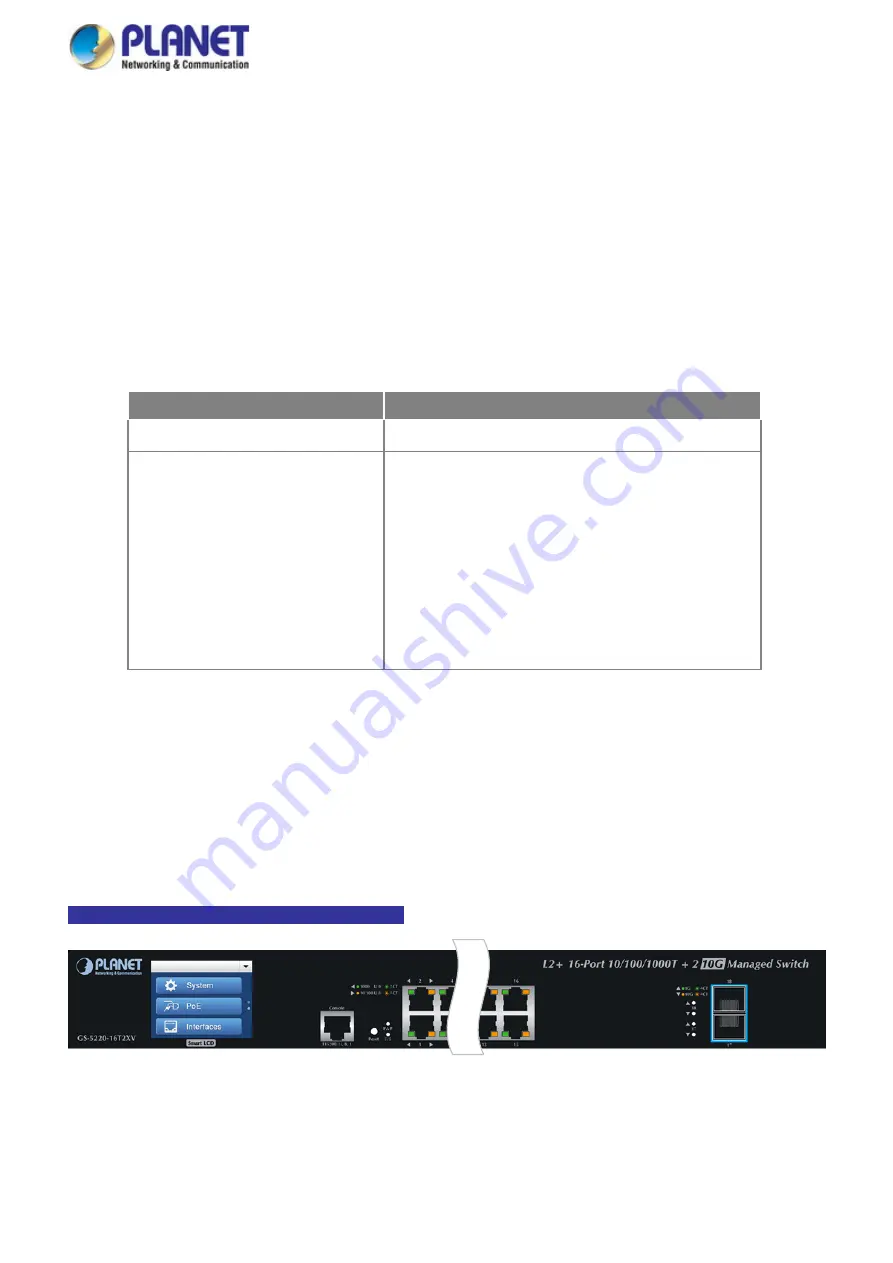
GS-5220-16T2XV / GS-5220-16T2XVR LED Indication
Figure 2-1-17:
GS-5220-16T2XV LED on Front Panel
Summary of Contents for GS-5220 Series
Page 1: ...User s Manual of GS 5220 LCD Series 1 GS 5220 Series L2 Gigabit 10 Gigabit Managed LCD Switch ...
Page 18: ...User s Manual of GS 5220 LCD Series 18 ...
Page 253: ...User s Manual of GS 5220 LCD Series 253 Figure 4 8 1 Multicast Service ...
Page 254: ...User s Manual of GS 5220 LCD Series 254 Figure 4 8 2 Multicast Flooding ...
Page 413: ...User s Manual of GS 5220 LCD Series 413 Figure 4 11 11 RADIUS Server Configuration Screenshot ...
Page 510: ...User s Manual of GS 5220 LCD Series 510 Figure 4 16 8 LLDP Configuration Screenshot ...