


3 Product Description
26
Version: 1.2.1
MS249E
C-863.12 Mercury Controller
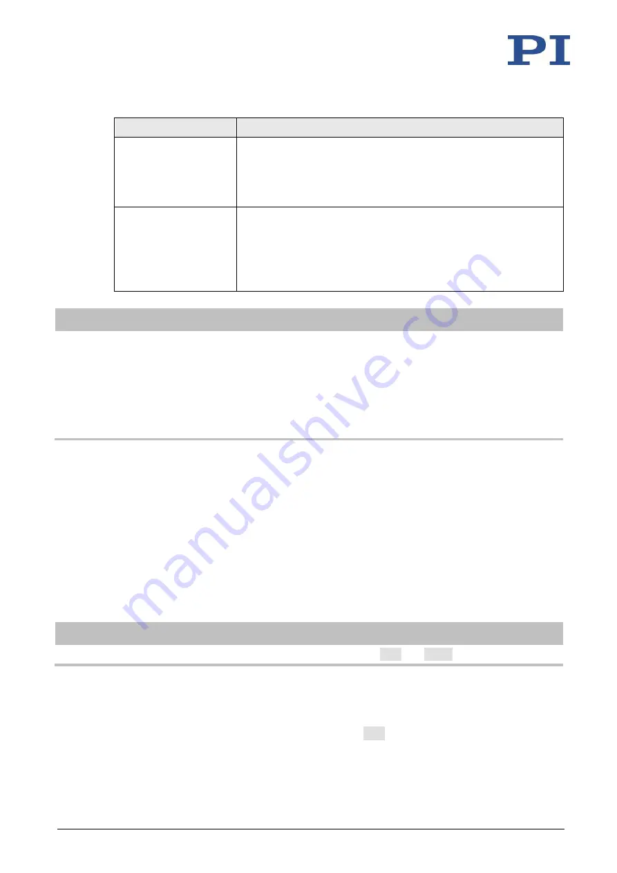
Parameter
Description and Possible Values
Distance From
Reference Position To
Positive Limit (Phys.
Unit)
0x2F
Gap between reference switch and positive limit switch (physical
unit)
If the axis has performed a reference move to the positive limit
switch, the current position is set to the sum of the values of
parameters 0x16 and 0x2F.
Maximum Travel In
Negative Direction
(Phys. Unit)
0x30
Soft limit in a negative direction (physical unit)
Based on the zero position. If this value is larger than the position
value for the negative limit switch (which results from the difference
between the parameters 0x16 and 0x17), the negative limit switch
cannot be used for reference moves.
The value can be negative.
INFORMATION
The C-863.12 determines the soft limits from parameters 0x15 (
Maximum Travel In Positive
Direction (Phys. Unit)
) and 0x30 (
Maximum Travel In Negative Direction (Phys. Unit)
):
▪
The limits establish the permissible travel range in closed-loop operation.
▪
Motion commands are executed only if the commanded position is within these soft limits.
▪
The limits always refer to the current zero position.
▪
Appropriate values are loaded when the positioner type is selected from the positioner
database.
Examples
The following examples refer to an axis of a positioner with incremental sensor, reference
switch and limit switches.
The distance between the negative and positive limit switches of the axis is 20 mm. The
reference switch has a distance of 8 mm to the negative limit switch and a distance of 12 mm to
the positive limit switch.
This switch setup of the axis is reflected in the following parameters:
▪
Parameter 0x17: Distance between negative limit switch and reference switch = 8 mm
▪
Parameter 0x2F: Distance between reference switch and positive limit switch = 12 mm
INFORMATION
The switch setup of the axis can be determined with the
FED
and
POS?
commands.
Example 1: Maximum travel range available
After reference moves (p. 28), the current position is to have the following values:
▪
Move to the negative limit switch (start with
FNL
): current position = 0