PI MS249E User Manual Download Page 244


9 Adapting Settings 

238 

Version: 1.2.1 

MS249E 

C-863.12 Mercury Controller 

3.


Click 

Keep the changes temporarily

 in the 

Save all changes permanently

 dialog to load 

the parameter settings into the volatile memory of the C-863.12. 

The 

Start up stages/axes

 window changes to the 

Start up axes

 step. 

4.


Click 

Close

 in the 

Start up axes

 step to close the 

Start up stages/axes

 window. 

5.


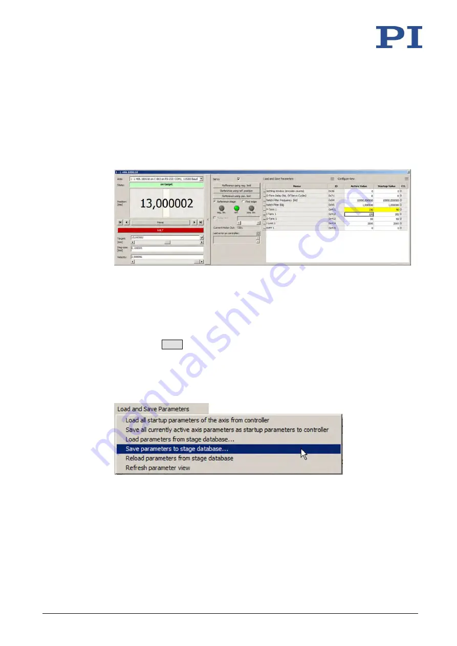
Open the expanded single axis window for the selected positioner in the main window 
of PIMikroMove by clicking the right mouse button on the corresponding line of the 

Axes

 tab and selecting 

Show Expanded Single Axis Window

 in the context menu. 


6.


Enter new values for the parameters to be changed: 

a)


If the parameter to be modified is not included in the list on the right-hand side of 
the window, click 

Configure view > Select parameters...

 and add it to the list. You 

can also display certain groups of parameters or all axes-related parameters. 

b)


Type the new parameter value into the corresponding input field in the 

Active 

Value

 column of the list. 

c)


Press the 

Enter

 key on the PC keyboard or click outside the input field with the 

mouse to transfer the parameter value to the volatile memory of the controller. 
Note: If a parameter value in the volatile memory (

Active Value

 column) is different 

to the parameter value in the nonvolatile memory (

Startup Value

 column), the line 

in the list is highlighted in color. 

7.


Click 

Load and Save Parameters -> Save parameters to stage database...


The 

Save Parameters as User Stage Type

 dialog opens. 

8.


Save the changed parameter values as new positioner type in the 

Save Parameters as 

User Stage Type

 dialog: 

a)


Leave the entry in the 

Parameters of axis

 field unchanged. 

b)


Enter the name for the new positioner type into the 

Save as

 field. 

c)


Click 

OK

Summary of Contents for MS249E

Page 1: ...ax 49 721 4846 1019 Email info pi ws www pi ws MS249E C 863 12 Mercury Controller User Manual Version 1 2 1 Date 19 10 2021 This document describes the following product C 863 12 Mercury servo control...

Page 2: ...marks of other owners Linux MATLAB MathWorks The patents held by PI are found in our patent list https www physikinstrumente com en about pi patents The software products provided by PI are subject to...

Page 3: ...cessories 10 3 5 Functional Principles 11 3 5 1 Block Diagram 11 3 5 2 Motor Control 11 3 5 3 Commandable Elements 12 3 5 4 Important Components of the Firmware 14 3 5 5 Operating Modes 15 3 5 6 Physi...

Page 4: ...cting Digital Inputs and Outputs 49 5 8 1 Connecting the Digital Outputs 49 5 8 2 Connecting the Digital Inputs 49 5 9 Connecting Analog Signal Sources 50 6 Startup 51 6 1 General Notes on Startup 51...

Page 5: ...Analog Inputs 88 7 5 2 Using Analog Input Signals in Macros 89 7 6 Joystick Control 89 7 6 1 How Joystick Control Works 89 7 6 2 Commands and Parameters for Joystick Control 90 7 6 3 Controlling Axis...

Page 6: ...249 10 1 Cleaning the C 863 12 249 10 2 Updating Firmware 249 11 Troubleshooting 255 12 Customer Service 259 13 Technical Data 261 13 1 Specifications 261 13 1 1 Data Table 261 13 1 2 Maximum Ratings...

Page 7: ...4 on our website 1 2 Symbols and Typographic Conventions The following symbols and typographic conventions are used in this user manual NOTICE Dangerous situation Failure to comply could cause damage...

Page 8: ...ere the first controller is connected directly to the PC The additional controllers are always connected to the ones that precede them so that a chain is formed The signal to and from a controller goe...

Page 9: ...ween the individual axes In this manual actuators i e drive components without a motion platform e g precision linear actuators are designated as positioners as well Control value The control value is...

Page 10: ...are A000T0081 Technical Note 1 6 Downloading Manuals INFORMATION If a manual is missing or problems occur with downloading Contact our customer service department p 259 Downloading Manuals 1 Open the...

Page 11: ...er manual The user is responsible for process validation 2 2 General Safety Instructions The C 863 12 is built according to state of the art technology and recognized safety standards Improper use can...

Page 12: ...ive the C 863 12 to other users also include this user manual as well as other relevant information provided by the manufacturer Always work according to the complete user manual The equipment can be...

Page 13: ...network do not connect to the PC if the USB interface is already connected RS 232 Out D sub 9 f p 269 Serial connection to the subsequent controller in a daisy chain network STA LED green Controller s...

Page 14: ...able p 270 Connector for the supply voltage I O Mini DIN 9 pole f p 266 Digital inputs outputs Outputs Trigger external devices Inputs Use in macros or as switch signals Analog inputs Use in macros or...

Page 15: ...he left 1 internal information 2 and 3 year of manufacture 4 to 9 consecutive number Country of origin Germany Country of origin Warning sign Pay attention to the manual Old equipment disposal p 271 C...

Page 16: ...e p 95 C 819 20Y Y cable for connecting 2 controllers to C 819 20 joystick C 819 30 Analog joystick for 3 axes details see Joysticks Available p 96 C 170 PB Pushbutton box with 4 buttons and 4 LEDs Co...

Page 17: ...C 863 12 is only as high as its supply voltage To avoid damaging the motor by excessive operating voltage the C 863 12 scales its output voltage to the motor connected Details on scaling The C 863 12...

Page 18: ...ionless 0 to 32767 The value 32767 standard corresponds to the maximum permissible operating voltage of the motor which is specified by parameter 0x7C The standard value of parameter 0x9 should not be...

Page 19: ...y digital output lines 1 to 4 of the I O socket p 266 For further information see Digital Output Signals p 76 Digital inputs 4 1 to 4 1 to 4 identify digital input lines 1 to 4 of the I O socket p 266...

Page 20: ...r the controller is switched on or rebooted the active command level is always 0 On command levels 1 write access is only available to PI service personnel Profile generator and servo algorithm In clo...

Page 21: ...position sensor As a result the positioner can move unbraked to the end of the travel range and despite the limit switch function strike the hard stop INFORMATION The C 863 12 is intended for closed l...

Page 22: ...and output scaling of position values The unit symbol can be customized for display purposes with the following parameter Parameters Description and Possible Values Axis Unit 0x07000601 Unit symbol M...

Page 23: ...ontent and motion commands received from the command line can overwrite each other Additional macro commands and information see Controller Macros p 97 Joystick control The joystick controls the veloc...

Page 24: ...ration in closed loop operation parameter 0xC physical unit of length s2 change with the DEC command or with SPA SEP can be saved with WPA Is limited by parameter 0x4B maximum deceleration in closed l...

Page 25: ...zoidal velocity profiles The axis accelerates linearly based on the acceleration value specified until it reaches the specified velocity It continues to move with this velocity until it decelerates li...

Page 26: ...ion parameters are changed during the course of the motion the acceleration value is used until the maximum velocity is reached and the deceleration value is used for the decrease in velocity down to...

Page 27: ...PID servo algorithm proportional integral derivative Dynamics profile corrections The dynamics profile generated can be subject to an offset correction and a feed forward control of the velocity Rega...

Page 28: ...servo control parameters from the encoder resolution The servo loop input factor is independent of the factor for counts per physical length unit 0xE and 0xF Numerator and denominator of the servo loo...

Page 29: ...ed as not reached The C 863 12 determines the on target state on the basis of the following criteria Settling window around the target position parameter 0x36 Delay time for setting the on target stat...

Page 30: ...reference switch Reference Signal Type 0x70 Reference signal type 0 Direction sensing reference switch default setting The signal level changes when passing the reference switch 1 Pulse signal with a...

Page 31: ...n also be used for reference moves After a reference move to a limit switch the controller knows the absolute axis position see Referencing p 28 3 5 13 Travel Range and Soft Limits The following param...

Page 32: ...mits establish the permissible travel range in closed loop operation Motion commands are executed only if the commanded position is within these soft limits The limits always refer to the current zero...

Page 33: ...set as follows Parameter 0x15 20 Parameter 0x30 0 Figure 8 The travel range of the axis is not limited by soft limits After a reference move of the axis to the reference switch FRF command query comm...

Page 34: ...rns the value 16 4 POS returns the value 5 4 3 5 14 Referencing When switching on or restarting the controller does not know the absolute position of the axis Before absolute target positions can be c...

Page 35: ...is overruns the edge of the switch overshooting 3 Move in the opposite direction to compensate for overshoot 4 Second move to the switch selected The maximum velocity is specified via parameter 0x50 V...

Page 36: ...meter ID 0x70 0 or 1 The approach always takes place from the same side irrespective of the axis position when the command is sent 2 The approach takes place via the negative limit switch FRF FRF Axis...

Page 37: ...limit switch and the hard stop Determines the maximum stopping distance during reference moves The actual velocities during a reference move are calculated on the basis of this value the set decelera...

Page 38: ...ee Using Digital Input Signals as Switch Signals p 86 for more information INFORMATION If the absolute position of the axis is defined manually with the POS command conflicts with the settings for the...

Page 39: ...3 Product Description C 863 12 Mercury Controller MS249E Version 1 2 1 33 3 6 Communication Interfaces 3 6 1 Controlling PI Systems Basically PI systems can be controlled as follows...

Page 40: ...ion Interlinking occurs in series See also Definition of Terms p 2 3 7 Overview of PC Software The following table shows the PC software on the PI software CD The specified operating systems stand for...

Page 41: ...for the USB interface For all users User software PC software Operating system Short description Recommended use PIMikroMove Windows Graphical user interface for Windows with which the C 863 12 and ot...

Page 42: ...ioner from a positioner database in the PC software from PI The PC software transfers the values of the selected parameter set to the volatile memory of the controller File name Description PISTAGES3...

Page 43: ...he contents with the scope of delivery according to the contract and the delivery note 3 Inspect the contents for signs of damage If any parts are damaged or missing contact our customer service depar...

Page 44: ......

Page 45: ...icking PISoftwareSuite exe in the installation directory root directory on the CD The InstallShield Wizard window opens for installing the PC software 2 Follow the instructions on the screen The PI so...

Page 46: ...ectory on the PI software CD Updating the PC software and PISTAGES3 DB in Windows Use the PI Update Finder Follow the instructions in the PI Update Finder manual A000T0028 Updating the PC software in...

Page 47: ...ileges 3 Install the update that you received from our customer service department onto your PC 5 1 3 Installing Custom Positioner Databases PI provides a CD with a custom positioner that has the foll...

Page 48: ...Mounting the C 863 12 The C 863 12 can be used as benchtop device or mounted in any orientation on a surface The C 863 12 is stackable and can be installed in a control cabinet Figure 10 C 863 12 dime...

Page 49: ...tem 5 4 Connecting the Positioner NOTICE Damage if a wrong motor is connected Connecting a Positioner with stepper motor to a DC motor controller can cause irreparable damage Only connect a Positioner...

Page 50: ...2 has the following interfaces for this purpose RS 232 interface USB interface In this section you learn how to establish proper cable connections between the C 863 12 and a PC and in a daisy chain ne...

Page 51: ...nterface of the PC a D sub 9 m panel plug to the null modem cable 5 5 2 Connecting to the USB Interface NOTICE Incorrect wiring Connecting the USB and RS 232 interfaces of the controller to the PC at...

Page 52: ...Baud Rate p 53 for details Tools and accessories A network cable for every controller to be connected to the network Currently available C 862 CN 30 cm included in the scope of delivery C 862 CN2 180...

Page 53: ...the PWM amplifier Requirements The power cord is not connected to the power socket Tools and accessories Wide input range power supply p 9 included for line voltages between 100 and 240 volts alterna...

Page 54: ...nalog joystick from PI for operation with 0 to 3 3 V available as an optional accessory p 10 C 819 20 analog joystick for 2 axes If a C 819 20 joystick is to be connected to two controllers C 819 20Y...

Page 55: ...ORMATION If the C 170 PB pushbutton box from PI is connected to the I O socket it displays via LEDs the state of the digital output lines Tools and accessories Suitable cable e g C 170 IO IO cable wit...

Page 56: ...pins 1 2 3 or 4 of the I O socket of the C 863 12 5 9 Connecting Analog Signal Sources The analog inputs on the I O socket of the C 863 12 can be used as follows Use in macros p 89 Details and exampl...

Page 57: ...purpose use the 24 STP or HLT command or set the control value to zero with the SMO command Do not disable the evaluation of the limit switches by the C 863 12 via parameter setting Check the functio...

Page 58: ...P switch settings Put the individual DIP switches in the correct position for your application Details are specified in the following tables 6 2 2 Controller Address Address S1 S2 S3 S4 1 ON ON ON ON...

Page 59: ...ler must have address 1 if it is to be used in PIMikroMove is to be used in drivers for NI LabVIEW software is to be addressed with PITerminal without specifying the target address in this case the ta...

Page 60: ...tes on startup p 51 The C 863 12 has been installed properly p 39 You have set the DIP switches on the C 863 12 in accordance with your application p 51 Switching the C 863 12 on Plug the power cord o...

Page 61: ...ood the general notes on startup p 51 The C 863 12 is connected to the RS 232 interface of the PC p 44 You have made the following settings with the respective DIP switches prior to switching on the C...

Page 62: ...63 12 This adapts the baud rate of the PC to the baud rate of the C 863 12 6 Click Connect to establish communication If communication was established successfully PIMikroMove guides you through the c...

Page 63: ...tart up controller window opens with the Connect controller step If the Start up controller window does not open automatically select the Connections New menu item in the main window Figure 13 Start u...

Page 64: ...which is connected to the PC 2 Connect the daisy chain network to the PC via the USB interface of this controller Requirements You have read and understood the general notes on startup p 51 You have...

Page 65: ...e window If you have connected the first controller in the chain to the PC via the RS 232 interface select the RS 232 Daisy Chain tab If you have connected the first controller in the chain to the PC...

Page 66: ...stablish communication with the controller selected When communication has been successfully established PIMikroMove guides you through the configuration of the C 863 12 for the connected positioner P...

Page 67: ...ports controllers with older firmware versions that are not compatible with GCS Make sure that the Mercury button is not activated in PITerminal 1 Start PITerminal 2 Click on Connect The Connect windo...

Page 68: ...dress 2 For further information see Target and Sender Address p 117 6 5 Starting Motion PIMikroMove is used in the following to move the positioner The program guides you through the following steps s...

Page 69: ...2 in the volatile memory during the process avoid saving the new settings in the nonvolatile memory of the C 863 12 The original settings are active again after the C 863 12 has been switched off and...

Page 70: ...ith PIMikroMove between the C 863 12 and the PC p 54 Starting motion with PIMikroMove 1 If in PIMikroMove the Select connected stages step is displayed select the positioner type of the positioner con...

Page 71: ...he Start up axes step perform the reference move for the axis so that the controller knows the absolute axis position If you want to start the reference move to the reference switch click Ref switch I...

Page 72: ...um P I D controller settings depend on your application and your requirements As a rule optimization occurs empirically and involves the following parameters For details see Servo Algorithm and Other...

Page 73: ...t checked the servo mode is switched off Click the checkbox to switch on the servo mode 3 Configure the data recorder a Set the size of the step to be made to a value that is typical for your applicat...

Page 74: ...yed graphically 5 Check the displayed step response see examples below If necessary enlarge the view by clicking the button and while pressing the left mouse button dragging the mouse pointer which ha...

Page 75: ...mal settling behavior commanded and actual position congruent If the result is satisfactory i e minimum overshoot settling time not too long You already have optimum parameter settings and do not have...

Page 76: ...input field in the Active Value column of the list c Press the Enter key on the PC keyboard or click outside the input field with the mouse to transfer the parameter value to the volatile memory of th...

Page 77: ...s to stage database in the expanded single axis window see Creating or Changing a Positioner Type p 236 Transfer the current values of the listed parameters from the volatile memory to the nonvolatile...

Page 78: ......

Page 79: ...current position and the commanded position exceeds the specified maximum value in closed loop operation The range in which the deviation may lie is specified by the Maximum Position Error Phys Unit p...

Page 80: ...itching on the servo mode the target position is set to the current axis position and the brake is deactivated if necessary Now the axis can move again and you can command a new target position INFORM...

Page 81: ...63 12 record the following Data recorder table 1 Record option 1 Commanded position of the axis Data recorder table 2 Record option 2 Current position of the axis Data recorder table 3 Record option 3...

Page 82: ...ber of points in the last recording with the DRL command p 147 7 3 Digital Output Signals The digital outputs of the C 863 12 are available at the I O socket p 266 Get the number of the output lines a...

Page 83: ...On Target The on target state of the axis selected is output at the selected trigger output p 80 5 Motion Error The selected digital output line becomes active when a motion error occurs p 80 The lin...

Page 84: ...tal output line TrigOutID that is to be used as the trigger output Send CTO TrigOutID 2 A where A indicates the axis to be moved Send CTO TrigOutID 3 0 where 0 specifies the Position Distance trigger...

Page 85: ...d TRO TrigOutID 1 Example A pulse on digital output line 1 is output every time the axis 1 of the positioner has covered a distance of 0 1 m as long as axis 1 is moving in positive direction of motion...

Page 86: ...s suitable for monitoring motion The selected digital output line becomes active when a motion error occurs on one of the connected axes The line stays active until the error code is reset to 0 by an...

Page 87: ...gger pulses are output respectively when the axis position equals the sum of the last valid trigger position and a specified distance TriggerStep The trigger output is stopped when a stop value is rea...

Page 88: ...en be output on this line every time axis B has covered a distance of 1 m in the negative direction The last trigger pulse is to be output if the absolute axis position is 0 1 mm Send CTO 2 2 B CTO 2...

Page 89: ...output send TRO TrigOutID 1 Example Digital output line 1 is to become active when the absolute position of axis 1 is at least 1 5 mm Send CTO 1 2 1 CTO 1 3 8 CTO 1 10 1 5 7 3 8 Setting Signal Polari...

Page 90: ...Variable CMD Copies the state of a digital input line to a variable when used in conjunction with the DIO query command Use in macros to set local variables p 118 DIO DIO DIOID Gets the state of the d...

Page 91: ...f the reference signal for the FRF and FED commands 0 reference switch 1 Digital input 1 2 Digital input 2 3 Digital input 3 4 Digital input 4 Source Of Negative Limit Signal 0x5D Specifies the source...

Page 92: ...mp of the macro pointer Copying the input state to a variable Further information and examples can be found in Controller Macros p 97 INFORMATION You can connect the C 170 PB pushbutton box from PI to...

Page 93: ...invert the signal logic of the digital input lines by setting parameters Invert Digital Input Used For Negative Limit ID 0x5F and Invert Digital Input Used For Positive Limit ID 0x60 accordingly INFOR...

Page 94: ...the I O socket can also be used as digital inputs Analog 0 to 5 V Digital TTL 7 5 1 Commands for Analog Inputs The following commands are available for the use of analog inputs Command Syntax Functio...

Page 95: ...e profile generator The relationship between the displacement of the joystick axis and the velocity of the positioner axis is established by the C 863 12 using a lookup table The 256 values in the loo...

Page 96: ...ckID JoystickAxis Gets the current state of a joystick axis displacement JBS JBS JoystickID JoystickButton Gets the current state of a joystick button pressed or not pressed JDT JDT JoystickID Joystic...

Page 97: ...applications Details and examples of macros are found in Controller Macros p 97 INFORMATION The C 863 12 supports one logical axis and is therefore normally used with positioners that only have one m...

Page 98: ...Configure Controller Joystick window 7 6 4 Calibrating the Joystick Calibration of the individual joystick axes is recommended after connecting a joystick to the C 863 12 for the first time Calibrati...

Page 99: ...r calibrating the Z axis Repeat calibration of the Z axis if you are connecting the Z axis to another controller INFORMATION The parabolic lookup table type allows greater sensitivity at low velocity...

Page 100: ...e the parabolic lookup table type for the joystick axis click Use Parabolic Standard Lookup Table With this the appropriate lookup table type is loaded and the calibration is finished If you have conn...

Page 101: ...d in the following as optional accessories p 10 Analog C 819 20 joystick 2 axes Figure 21 C 819 20 joystick 1 2 3 4 5 6 7 Pushbutton for the X axis Pushbutton for the Y axis Adjustment indicator Rotar...

Page 102: ...Cable for the Y axis Cable for the X axis Adjustment indicator Pushbutton for the Y axis Rotary knob for adjustment of the Y axis calibration XY control lever with rotary knob for Z axis X axis lock...

Page 103: ...ible Macros can call up themselves or other macros Variables p 118 can be set for the macro and in the macro itself and used in different operations Input signals can be evaluated for conditions and v...

Page 104: ...er macro name can consist of up to 8 characters MAC DEF macro name Defines the specified macro as the startup macro MAC DEF Gets the startup macro MAC DEL macro name Deletes the specified macro MAC EN...

Page 105: ...is stopped if an error occurs when it is running 0 Stop macro when error occurs default 1 Ignore error 7 7 3 Working with Macros Work with macros comprises the following Recording macros p 99 Startin...

Page 106: ...working with PIMikroMove or have established communication with PITerminal using the GCS DLL button the target address is automatically sent and may not be typed in INFORMATION To make the use of macr...

Page 107: ...whether the macro has been correctly recorded If you are working with PITerminal or in the Command entry window of PIMikroMove Get which macros are saved in the C 863 12 by sending the MAC command Get...

Page 108: ...ing PITerminal whereby communication was established with the Connect button as a result the target address has to be typed in in every command line The servo mode is to be switched on for axis 1 via...

Page 109: ...atus can have the value 0 or 1 0 Stop macro when error occurs default 1 Ignore macro error Further information on changing parameters can be found in Adapting Settings p 231 2 Start the macro If the m...

Page 110: ...memory of the C 863 12 2 Record the MOVLR macro by sending MAC BEG movlr MAC START movwai LEFT MAC START movwai RIGHT MAC END MOVLR successively starts the MOVWAI macro which is still to be recorded...

Page 111: ...h the value 1 After this the TESTDION macro is started for the input line whose identifier is specified via the COUNTER variable Then the value of the COUNTER is increased by 1 As long as the value of...

Page 112: ...d MAC DEF Get the name of the currently defined startup macro by sending the MAC DEF command Example Preparing an axis for operation via a startup macro INFORMATION When macros are recorded on the Con...

Page 113: ...d for backing up and loading controller macros A detailed description of the tab can be found in the PIMikroMove manual Backing up controller macros onto the PC with PIMikroMove 1 Select the Controlle...

Page 114: ...n assignment see I O p 266 The digital output signal of the master controller can be used as the trigger for the motion of the axis connected to the slave controller Set up the motion on the master co...

Page 115: ...ect digital input line 1 on the I O socket to an appropriate signal source Pin assignment see I O p 266 For example the digital input signal can be used for a conditional jump of the macro pointer Rec...

Page 116: ...o be activated only when the joystick button is pressed at the same time By using the buttons of a connected pushbutton box in addition up to four positions are to be stored in the controller or appro...

Page 117: ...mainloop MAC START TESTJOYB VAR COUNTER 1 MAC START TESTDION COUNTER ADD COUNTER COUNTER 1 JRC 2 VAR COUNTER 5 MAC START MAINLOOP MAC END The macro has the following tasks Start TESTJOYB macro for jo...

Page 118: ...value of the local variable 1 is also used for local variable 1 in MVAX2ST MVAX2ST moves axis 1 to the position assigned for the button MEX DIO 1 0 Stop macro execution if button is no longer pressed...

Page 119: ...box until the button LED lights up 7 7 8 Macro Example Joystick Control with Change in Velocity INFORMATION When macros are recorded on the Controller macros tab in PIMikroMove the MAC BEG and MAC END...

Page 120: ...essed jump 2 lines back to set up a loop VEL 1 1 Maximum velocity during joystick control is 1 JRC 4 JON 1 1 If joystick 1 is still active jump 4 lines back to set up a loop MAC END Start the JOYVEL m...

Page 121: ...pace character Quotation marks indicate that the characters enclosed are returned or to be entered 8 2 GCS Syntax for Syntax Version 2 0 A GCS command consists of 3 characters e g CMD The correspondin...

Page 122: ...controller e g m or mm Send MOVSP1SP10 0LF More than one command mnemonic per line is not allowed Several groups of arguments following a command mnemonic are allowed Example 2 Two axes connected to t...

Page 123: ...ending command line SEP 100 1 0x32 0 1 0x14 1 is not possible however because two parameters are to be changed If the command supports this all elements can be addressed by omitting the element identi...

Page 124: ...PI Karlsruhe C 863 11 0 1 2 0 0 Send 1 IDN The same controller responds with 0 1 c 2011 Physik Instrumente PI Karlsruhe C 863 11 0 1 2 0 0 See Adapting DIP Switch Settings p 51 on how to set the contr...

Page 125: ...ables 0 1 and 2 The values of the local variables 1 and 2 are specified as arguments of the MAC START or MAC NSTART command when starting the macro The command formats are MAC START macroname String1...

Page 126: ...Axes IDN p 128 IDN Get Device Identification ACC p 129 ACC AxisID Acceleration Set Closed Loop Acceleration ACC p 129 ACC AxisID Get Closed Loop Acceleration ADD p 130 ADD Variable FLOAT1 FLOAT2 Add...

Page 127: ...DIOID Get Digital Input Lines DRC p 145 DRC RecTableID Source RecOption Set Data Recorder Configuration DRC p 147 DRC RecTableID Get Data Recorder Configuration DRL p 147 DRL RecTableID Get Number Of...

Page 128: ...X JoystickID JoystickAxis AxisID Set Axis Controlled By Joystick JAX p 163 JAX JoystickID JoystickAxis Get Axis Controlled By Joystick JBS p 164 JBS JoystickID JoystickButton Query Joystick Button Sta...

Page 129: ...For Command MAT p 175 MAT Variable FLOAT1 OP FLOAT2 Calculate And Save To Variable MEX p 176 MEX CMD OP Value Stop Macro Execution Due To Condition MOV p 177 MOV AxisID Position Set Target Position M...

Page 130: ...emID PamID Get Nonvolatile Memory Parameters SMO p 188 SMO AxisID ControlValue Set Open Loop Control Value SMO p 189 SMO AxisID Get Control Value SPA p 190 SPA ItemID PamID PamValue Set Volatile Memor...

Page 131: ...Output State TRO p 200 TRO TrigOutID Get Trigger Output State TRS p 201 TRS AxisID Indicate Reference Switch TVI p 201 TVI Tell Valid Character Set For Axis Identifiers VAR p 202 VAR Variable String S...

Page 132: ...following codes in hexadecimal format Bit 15 14 13 12 11 10 9 8 Descript ion On target state Is referencing In motion Servo mode on Error flag Bit 7 6 5 4 3 2 1 0 Descript ion Digital in put line 4 Di...

Page 133: ...and the second axis are in motion 7 Request Controller Ready Status Description Asks controller for ready status tests if controller is ready to run a new command Note Use 5 p 127 instead of 7 to ver...

Page 134: ...s 24 stops all motion caused by motion commands e g MOV p 177 MVR p 179 GOH p 157 STE p 194 SMO p 188 commands for referencing FNL p 153 FPL p 154 FRF p 155 and macros MAC p 171 Also stops macro runni...

Page 135: ...vo mode ON The lowest possible value for Acceleration is 0 ACC changes the value of the Closed Loop Acceleration Phys Unit s2 parameter ID 0xB in the volatile memory of the C 863 12 The parameter valu...

Page 136: ...he result is to be saved FLOAT1 is the first summand FLOAT2 is the second summand Floating point numbers are expected for the summands They can be specified directly or via the value of a variable Res...

Page 137: ...when starting the macros see below DIO 0 bitmask Sets the output channels according to bitmask For example DIO 0 5 activates channels 1 and 3 and deactivates all other channels 5 is 0000 0101 in bina...

Page 138: ...rake can only be used if parameter 0x1A Has Brake has the value 1 yes If parameter 0x1A Has Brake has the value 1 yes the following applies The brake can be activated or deactivated with BRA only if t...

Page 139: ...etermines the availability of commands and write access to system parameters Format CCL Level PSWD Arguments Level is a command level of the controller PSWD is the password required for changing to th...

Page 140: ...using parameters see Adapting Settings p 231 After controller switch on or reboot the active command level is always level 0 CCL Get Command Level Description Get the active command level Format CCL...

Page 141: ...ment of the MAC START or MAC NSTART command when starting the macro Write the connect macro MAC BEG connect CPY 1 DIO 0 DIO 0 1 MAC START CONNECT MAC END Example 2 It is possible to copy the value of...

Page 142: ...nfigures the trigger output conditions for the specified digital output line Format CTO TrigOutID CTOPam Value Arguments TrigOutID is one digital output line of the controller see below for details CT...

Page 143: ...es for StartThreshold and StopThreshold CTOPam IDs 8 and 9 can be defined to activate the trigger output for a limited position range and a certain direction of motion only negative or positive Note I...

Page 144: ...CTOPam ID 10 for Polarity default value is 1 sets the signal polarity for the digital output line 0 Active Low 1 Active High for StartThreshold StopThreshold position value if used for the PositionDis...

Page 145: ...he Position Offset trigger mode for both directions of motion in a range of 1 mm For that purpose two macros are written to the controller Macro TRIGREF initializes the controller and could also be de...

Page 146: ...s the values set for specified trigger output lines and parameters Format CTO TrigOutID CTOPam Arguments TrigOutID is a digital output line of the controller see CTO CTOPam parameter ID see CTO If all...

Page 147: ...Phys Unit s2 parameter ID 0xC in the volatile memory of the C 863 12 The parameter value can be stored as default with WPA p 205 for details see Adapting Settings p 231 The maximum value that can be s...

Page 148: ...position If no arguments are specified DFH defines the zero position of all axes Format DFH AxisID Arguments AxisID is one axis of the controller Response none Troubleshooting Illegal axis identifier...

Page 149: ...MX are queried Send DFH 1 Send POS 1 Receive 1 0 0000000 Send DFH 1 Receive 1 9 8700005 Send TMN 1 Receive 1 9 8700005 Send TMX 1 Receive 1 5 1299978 Note The axis has not moved The current axis posit...

Page 150: ...axes During referencing For the affected axis See DFH for an example DIO Set Digital Output Line Description Switches the specified digital output line s to specified state s Use TIO p 198 to get the...

Page 151: ...OID InputOn LF where InputOn specifies the state of the digital input line see below for details Notes You can use the DIO command to read digital input lines 1 to 4 on the I O socket directly p 266 T...

Page 152: ...s and additional information on the data recording The number of available data recorder tables can be read with TNR p 199 Refer to Data Recorder p 74 for further information Recording options availab...

Page 153: ...rded Format DRC RecTableID Arguments RecTableID is a data recorder table of the controller if this entry is not specified the response will contain the settings for all tables Response The current DRC...

Page 154: ...cTableID Arguments StartPoint is the first point to be read from the data recorder table starts with index 1 NumberOfPoints is the number of points to be read per table RecTableID is one data recorder...

Page 155: ...002 5 00000 0 00000 5 00000 0 00000 5 00000 0 00000 5 00000 0 00000 5 00000 0 00000 4 99998 0 00002 5 00000 0 00000 4 99998 0 00002 5 00000 0 00000 5 00000 0 00000 5 00000 0 00000 5 00000 0 00000 4 99...

Page 156: ...p response measuring is done with STE p 194 With HDR p 157 you will obtain a list of all available record and trigger options and additional information on the data recording For further information s...

Page 157: ...ggerSource Value ERR Get Error Number Description Get error code int of the last occurred error and reset the error to 0 Only the last error is buffered You should therefore call ERR after each comman...

Page 158: ...Format FED AxisID EdgeID Param Arguments AxisID is one axis of the controller EdgeID is the type of edge the axis has to move to See below for available edge types Param depends on the selected edge a...

Page 159: ...otion commands like FED are not allowed when the joystick is active for the axis For further information see Joystick Control p 89 Available edge types and parameters The following edge types with the...

Page 160: ...be stopped by 24 p 128 STP p 195 and HLT p 158 Use FRF p 156 to check whether the reference move was successful For best repeatability referencing must always be done in the same way If soft limits p...

Page 161: ...limit switch as source of the positive limit switch signal for FPL For further information see Digital Input Signals p 83 Motion can be stopped by 24 p 128 STP p 195 and HLT p 158 Use FRF p 156 to ch...

Page 162: ...h as source of the reference signal for the FRF command For further information see Digital Input Signals p 83 The motion can be stopped by 24 p 128 STP p 195 and HLT p 158 Use FRF p 156 to check whet...

Page 163: ...cted with RON p 183 GOH Go To Home Position Description Moves the specified axis to the zero position GOH AxisID is the same as MOV AxisID 0 The motion can be stopped by 24 p 128 STP p 195 and HLT p 1...

Page 164: ...nd of help Note TriggerOptions 0 default means that recording is triggered by the STE command p 194 HLP Get List Of Available Commands Description Lists a help string which contains all commands avail...

Page 165: ...p 171 After the axes are stopped their target positions are set to their current positions HPA Get List Of Available Parameters Description Responds with a help string that contains all available para...

Page 166: ...ding value The parameters listed with HPA can be changed and or saved using the following commands SPA p 190 influences the parameter settings in volatile memory RAM WPA p 205 copies parameter setting...

Page 167: ...parameter not applicable for this item 1 enumeration 2 min max PossibleValue is a value from the permissible data range ValueDescription is the meaning of the corresponding value Some parameters are w...

Page 168: ...ow for details Notes A joystick can be connected to the Joystick p 268 socket of the C 863 12 the identifier is 1 The C 863 12 supports one axis of the joystick the identifier of the joystick axis is...

Page 169: ...le Elements p 12 for more information JAX Get Axis Controlled By Joystick Description Queries axis controlled by a joystick which is connected to the controller Format JAX JoystickID JoystickAxis Argu...

Page 170: ...connected to the Joystick p 268 socket of the C 863 12 the identifier is 1 The C 863 12 supports one button of the joystick the identifier of the joystick button is 1 Refer also to Commandable Elemen...

Page 171: ...nected to the controller The amplitudes of the joystick axes i e their displacements are mapped to the current valid velocity settings of the controller axes For each joystick axis there is a lookup t...

Page 172: ...sition of the joystick and in a small area around the center the velocity is 0 and the controlled axis will not move Point 236 has the value 0 8369 i e when the displacement of the joystick axis is ab...

Page 173: ...3 12 JoystickID and JoystickAxis must be left out in the JLT command but StartPoint and NumberOfPoints are always required The values floatn in the lookup table are factors that are applied to the vel...

Page 174: ...When a joystick connected to the C 863 12 is activated with the JON command this joystick controls the axis velocity commanded velocity output by the profile generator During joystick control the soft...

Page 175: ...k to the previous line 0 means the command is executed again which is the same behavior as with WAC p 205 1 jumps to the next line making the command unnecessary and 2 jumps over the next command Only...

Page 176: ...D is one axis of the controller Response AxisID uint LF where uint indicates whether the axis has limit switches 1 or not 0 Troubleshooting Illegal axis identifier Notes The C 863 12 firmware detects...

Page 177: ...the macro End the recording with MAC END Note that erroneous macro content cannot be detected by sending the ERR command MAC END Stops macro recording cannot become part of a macro MAC ERR RepoReports...

Page 178: ...cro contains a disallowed MAC command Notes Running a macro is not allowed when a macro is being recorded When a macro is recorded for a controller whose address is different from 1 the target address...

Page 179: ...eceived from the command line can overwrite each other Macro execution can be stopped with 24 p 128 and STP p 195 It is not possible to run several macros simultaneously Only one macro can be run at a...

Page 180: ...A string that describes the command Notes A detailed help text can be displayed for the following GCS commands CTO CTO WPA Example Send MAN CTO Receive CTO TrigOutID CTOPam Value Set Configuration Of...

Page 181: ...operator to be used The following operators are possible OP Operation Type Addition Mathematical operation Subtraction Mathematical operation Multiplication Mathematical operation AND UND Bit operatio...

Page 182: ...the macro interpreter accesses this command the condition is checked If it is true the current macro is stopped otherwise the macro continues to run with the next line Should the condition be fulfill...

Page 183: ...ction relative move KEY2 checks the state of the digital input channel 2 and moves axis 1 in negative direction accordingly By connecting the digital input channels 1 2 and 4 with pushbuttons e g with...

Page 184: ...d This is also valid with macros Motion commands can be sent from the command line when a macro is running The macro content and motion commands received from the command line can overwrite each other...

Page 185: ...ves the specified axis relative to the last commanded target position Format MVR AxisID Distance Arguments AxisID is one axis of the controller Distance specifies the distance that the axis is to move...

Page 186: ...nd MOV 1 Receive 1 0 500000 Send MVR 1 2 Note This is a relative motion Send POS 1 Receive 1 2 500000 Send MVR 1 2000 Note New target position of axis 1 would exceed motion range Command is ignored i...

Page 187: ...new current position in physical units Response None Troubleshooting Illegal axis identifier Notes It is only possible to set the current position with POS when the referencing method 0 is selected se...

Page 188: ...units Troubleshooting Illegal axis identifier RBT Reboot System Description Reboots system The controller behaves the same as after switching on Format RBT Arguments none Response none Notes RBT cann...

Page 189: ...ove can be started with FRF p 155 FNL p 153 or FPL p 154 Relative motion with MVR is possible even when referencing has not been done for the axis ReferenceOn 1 A reference move for the axis must be s...

Page 190: ...memory and SEP p 186 writes parameter settings directly into nonvolatile memory without changing the settings in volatile memory See SPA for an example Format RPA ItemID PamID Arguments ItemID is the...

Page 191: ...None Notes The duration of the recording can be calculated as follows Rec duration cycle time of the servo loop RTR value number of points where the cycle time of the servo loop for the C 863 12 is 50...

Page 192: ...is identifier can be stored permanently in the C 863 12 with the WPA p 205 command SAI Get List Of Current Axis Identifiers Description Queries the axis identifiers Refer also to Commandable Elements...

Page 193: ...atile memory See below for details PamID is the parameter identifier can be written in hexadecimal or decimal format See below for details PamValue is the value for setting the specified parameter of...

Page 194: ...e PamValue is the value of the specified parameter for the specified element Troubleshooting Illegal element identifier wrong parameter ID Notes With the C 863 12 you can query either all parameters o...

Page 195: ...ot be greater than the value of the Maximum Motor Output parameter 0x9 When this parameter is set to its maximum 32767 ControlValue ranges from 32766 to 32766 dimensionless The sign of the value deter...

Page 196: ...e Parameter changes are lost when the controller is switched off or rebooted Format SPA ItemID PamID PamValue Arguments ItemID is the element for which a parameter is changed in volatile memory See be...

Page 197: ...he P term of the servo algorithm for axis 1 to 100 the parameter ID is written in hexadecimal format Send SPA 1 1041 150 Note Sets the P term of the servo algorithm for axis 1 to 150 the parameter ID...

Page 198: ...Note Check the parameter settings in volatile memory SPA Get Volatile Memory Parameters Description Queries the value of a parameter of a specified element from volatile memory RAM You can obtain a l...

Page 199: ...ow for available registers Response ItemID RegisterID Value LF where Value is the value of the register see below for more details Note This command is identical in function to 4 p 126 which should be...

Page 200: ...the recorder tables can be set with DRC p 145 The recorded data can be read with the DRR command p 148 Format STE AxisID Amplitude Arguments AxisID is one axis of the controller Amplitude is the size...

Page 201: ...stopped their target positions are set to their current positions HLT p 158 in contrast to STP stops motion with specified system deceleration regarding system inertia SVO Set Servo Mode Description S...

Page 202: ...vation state of the brake Switching on the servo mode deactivates the brake Switching off the servo mode activates the brake When the servo mode is switched off the brake can be activated or deactivat...

Page 203: ...at TAV AnalogInputID Arguments AnalogInputID is the identifier of the analog input channel see below for details Response AnalogInputID float LF where float is the current voltage at the analog input...

Page 204: ...tput 4 lines can be set using the DIO command p 144 Furthermore you can program the Output 1 to Output 4 lines using the CTO command p 136 trigger configuration and the TRO command p 200 trigger activ...

Page 205: ...e AxisID float LF where float is the maximum commandable position in physical units Note The maximum commandable position is defined by the parameter 0x15 When redefining the zero position with the DF...

Page 206: ...e digital output lines Output 1 to Output 4 IDs 1 to 4 for further information see I O p 266 Do not use DIO p 144 on digital output lines where the trigger output is activated by TRO TRO Get Trigger O...

Page 207: ...nce switch FRF command p 155 according to the value of this parameter Adapt the parameter value to your hardware using SPA p 190 or SEP p 186 For further information see Reference Switch Detection p 2...

Page 208: ...t If not specified the variable is deleted The value can be specified directly or via the value of a variable Refer to Variables p 118 for more details on conventions regarding variable names and valu...

Page 209: ...onse Variable String LF where String gives the value to which the variable is set Notes Local variables can be queried using VAR only when a macro with local variables is running See Variables p 118 f...

Page 210: ...velocity If no arguments are specified queries the value of all axes Format VEL AxisID Arguments AxisID is one axis of the controller Response AxisID float LF where float is the currently valid veloci...

Page 211: ...e used The following operators are possible Important There must be a blank space before and after the operator value is the value to be compared with the response to CMD Response None Example Send MA...

Page 212: ...below for details ItemID is the element for which a parameter is to be saved from the volatile to the nonvolatile memory See below for details PamID is the parameter identifier can be written in hexa...

Page 213: ...command buffer overrun 4 PI_CNTR_SCAN_ERROR Error while scanning 5 PI_CNTR_MOVE_WITHOUT_REF_OR_NO_ SERVO Unallowable move attempted on unreferenced axis or move attempted with servo off 6 PI_CNTR_INVA...

Page 214: ...HAS_NO_REFERENCE Axis has no reference sensor 32 PI_CNTR_STAGE_HAS_NO_LIM_SWITCH Axis has no limit switch 33 PI_CNTR_NO_RELAY_CARD No relay card installed 34 PI_CNTR_CMD_NOT_ALLOWED_FOR_STA GE Command...

Page 215: ..._CNTR_INVALID_RECORDER_CHAN Data Record Table does not exist 58 PI_CNTR_INVALID_RECORDER_SRC_OPT Source does not exist number too low or too high 59 PI_CNTR_INVALID_RECORDER_SRC_CHAN Source Record Tab...

Page 216: ...6 PI_CNTR_IF_BUFFER_OVERRUN Interface buffer did overrun and command couldn t be received correctly 77 PI_CNTR_NOT_ENOUGH_RECORDED_DAT A Data Record Table does not hold enough recorded data 78 PI_CNTR...

Page 217: ...e name 97 PI_CNTR_INVALID_VALUE_LENGTH Invalid length of value too much characters 98 PI_CNTR_AUTOZERO_FAILED AutoZero procedure was not successful 99 PI_CNTR_SENSOR_VOLTAGE_OFF Sensor voltage is off...

Page 218: ...ION_BASED_ON_INTERPOL ATION Position was calculated during MOV motion 220 PI_CNTR_INTERPOLATION_FIFO_UNDERR UN FIFO buffer underrun during interpolation 221 PI_CNTR_INTERPOLATION_FIFO_OVERFLO W FIFO b...

Page 219: ...N_AC TIVATED The red knob is still set and disables system 501 PI_CNTR_EMERGENCY_STOP_BUTTON_W AS_ACTIVATED The red knob was activated and still disables system reanimation required 502 PI_CNTR_REDUND...

Page 220: ...s are not part of the same chain 543 PI_CNTR_NODE_MEMORY_FULL Unused nodes must be deleted before new nodes can be stored 544 PI_CNTR_PIVOT_POINT_FEATURE_NOT_S UPPORTED With some transformations pivot...

Page 221: ...ror 603 PI_CNTR_HW_TEMPERATURE_ERROR hardware temperature out of range 604 PI_CNTR_POSITION_ERROR_TOO_HIGH Position error of any axis in the system is too high 606 PI_CNTR_INPUT_OUT_OF_RANGE Maximum v...

Page 222: ...NTR_EXTERNAL_MODE_DRIVER_MISS ING External mode driver missing 718 PI_CNTR_CONFIGURATION_FAILURE_EXTE RNAL_MODE Missing or incorrect configuration of external mode 719 PI_CNTR_EXTERNAL_MODE_CYCLETIME_...

Page 223: ...IN_MACRO_MODE Command not valid during macro execution 1012 PI_CNTR_ERROR_IN_MACRO Error occured during macro execution 1024 PI_CNTR_MOTION_ERROR Motion error position error too large servo is switche...

Page 224: ...id 4007 PI_CNTR_FW_UPDATE_ERROR FW update failed 4008 PI_CNTR_FW_CRC_PAR_ERROR FW Parameter CRC wrong 4009 PI_CNTR_FW_CRC_FW_ERROR FW CRC wrong 5000 PI_CNTR_INVALID_PCC_SCAN_DATA PicoCompensation scan...

Page 225: ...riting to sensor 6002 PI_CNTR_SENSOR_ABS_READ_ERROR Error while reading from sensor 6003 PI_CNTR_SENSOR_ABS_CRC_ERROR Checksum error of absolute sensor 6004 PI_CNTR_SENSOR_ABS_ERROR General error of a...

Page 226: ...M_GPIB_ESAC IEEE488 Function requires GPIB board to be SAC 19 COM_GPIB_EABO IEEE488 I O operation aborted 20 COM_GPIB_ENEB IEEE488 Interface board not found 21 COM_GPIB_EDMA IEEE488 Error performing D...

Page 227: ...device not opened for erase 42 COM_FTDIUSB_DEVICE_NOT_OPENED_FO R_WRITE FTDIUSB device not opened for write 43 COM_FTDIUSB_FAILED_TO_WRITE_DEVIC E FTDIUSB failed to write device 44 COM_FTDIUSB_EEPROM_...

Page 228: ...V out of range must be in 1 10000 1003 PI_INVALID_SGA Invalid value for SGA must be one of 1 10 100 1000 1004 PI_UNEXPECTED_RESPONSE Controller sent unexpected response 1005 PI_NO_MANUAL_PAD No manual...

Page 229: ...SPA_CMD_ID Invalid parameter ID specified for SPA or SPA 1021 PI_NR_AVG_OUT_OF_RANGE Number for AVG out of range must be 0 1022 PI_WAV_SAMPLES_OUT_OF_RANGE Incorrect number of samples specified for WA...

Page 230: ...041 PI_PARAM_SET_ERROR Parameter could not be set with SPA parameter not defined for this controller 1042 PI_NUMBER_OF_POSSIBLE_WAVES_EXCEE DED The maximum number of wave definitions has been exceeded...

Page 231: ...ITOR_WRONG_IP_VALUE WaveEditor Error during wave creation incorrect index for integer parameter 1060 PI_WAVE_EDITOR_WRONG_DP_VALUE WaveEditor Error during wave creation incorrect index for floating po...

Page 232: ...ine the required device driver version 1075 PI_INVALID_LIBRARY_VERSION The library used doesn t match the required version Please refer to the documentation to determine the required library version 1...

Page 233: ...of input arguments 1092 PI_FAILED_TO_CHANGE_CCL_LEVEL Change of command level has failed 1093 PI_FAILED_TO_SWITCH_OFF_SERVO Servo mode has failed to switch off 1094 PI_FAILED_TO_SET_SINGLE_PARAMETER_...

Page 234: ...I_PARAMETER_DB_INVALID_STAGE_TYPE _FORMAT PI stage database String containing stage type and description has invalid format 10001 PI_PARAMETER_DB_SYSTEM_NOT_AVAIL ABLE PI stage database Database does...

Page 235: ...via PIUpdateFinder No parameters were set 10012 PI_PARAMETER_DB_AND_HPA_MISMATC H_STRICT Mismatch between number of parameters present in stage database and available in controller interface No param...

Page 236: ......

Page 237: ...havior of the system The designation Active Values is used for the parameter values in the volatile memory and Startup Values is used for the parameter values in the nonvolatile memory in the PC softw...

Page 238: ...Responds with a help string that contains all available parameters with short descriptions RPA Copy a parameter value from the nonvolatile to the volatile memory SEP Change parameters in the nonvolat...

Page 239: ...ics INFORMATION Parameter values saved in a text file on the PC can be loaded back to the C 863 12 in PIMikroMove or PITerminal The Send file button is available for this purpose in the send command w...

Page 240: ...ng the C 863 12 and take effect immediately Unsuitable parameter settings can cause damage to the connected mechanics Change parameter values only after careful consideration Save the current paramete...

Page 241: ...ght mouse button on the corresponding line of the Axes tab and selecting Show Expanded Single Axis Window in the context menu b If the parameter to be modified is not included in the list on the right...

Page 242: ...Save Parameters Save all currently active axis system parameters as startup parameters to controller to write the values of all axis related system related parameters from the volatile to the nonvolat...

Page 243: ...atabase for your positioner the dataset was imported into PIStages3 p 41 You have established communication with PIMikroMove between the C 863 12 and the PC p 54 Creating a positioner type in the posi...

Page 244: ...ick Configure view Select parameters and add it to the list You can also display certain groups of parameters or all axes related parameters b Type the new parameter value into the corresponding input...

Page 245: ...positioner type in the positioner database 4 Save the modified parameter values of the positioner type in the Save Parameters as User Stage Type dialog a Leave the entry in the Parameters of axis fiel...

Page 246: ...for write access Element Element type to which the parameter refers for more information see Commandable Items p 12 Parameter name Name of the parameter Description Explanation of the parameter ID Typ...

Page 247: ...o evaluation by the C 863 12 but only by the PC software PIMikroMove determines which motion is permissible on the basis of this value 0x14 INT 0 Axis Has Reference Does the positioner have a referenc...

Page 248: ...eference switch and positive limit switch See examples in Travel Range and Soft Limits p 26 0x30 FLOAT 0 Axis Maximum Travel In Negative Direction Phys Unit Soft limit in a negative direction See exam...

Page 249: ...operation Limited by parameter 0xA For details see Generation of Dynamics Profile p 18 0x4A FLOAT 0 Axis Maximum Closed Loop Acceleration Phys Unit s2 Maximum acceleration in closed loop operation Sp...

Page 250: ...uts that are used as the source of the negative limit switch signal For details see Commands and Parameters for Digital Inputs p 84 and Using Digital Input Signals as Switch Signals p 86 0x60 INT 0 Ax...

Page 251: ...tails see Referencing p 28 0x79 FLOAT 0 Axis Distance For Reference Search Phys Unit Maximum distance for the reference move to the index pulse For details see Referencing p 28 0x7C FLOAT 0 Axis Maxim...

Page 252: ...er than the value of parameter 0x3095 To prevent heat from building up too much continuous supply of voltage to the brake should be kept as low as possible Is only used when parameters 0x1A and 0x3094...

Page 253: ...ervo Update Time Servo cycle time in seconds 0x0F000100 CHAR 2 Axis Stage Type Positioner type Format for standard positioners x xxx Format for customized positioners x xxxKxxx 0x0F000200 CHAR 2 Axis...

Page 254: ......

Page 255: ...ay mean that the C 863 12 can only be made operational again by the PI customer service department Update the C 863 12 s firmware only after consulting our customer service department If possible ask...

Page 256: ...ustomer service department together with the new firmware You have learned from the documentation whether new parameters are introduced with the firmware update or the memory management of the C 863 1...

Page 257: ...ller 5 Select the new firmware file a Click the Select button b Go to the directory in the file selection window where you stored the firmware file c Double click the new firmware file hex extension t...

Page 258: ...changed If no Firmware update is finished If yes Initialization of the C 863 12 is required see below Initializing the C 863 12 after a firmware update The initialization of the C 863 12 resets all p...

Page 259: ...s General Procedure p 234 Reset the parameters that were already present prior to the firmware update to the saved values from the text file Set the parameters that were introduced with the firmware u...

Page 260: ......

Page 261: ...r adapter for the PWM amplifier Make sure that the power adapter is functioning properly Limit switch signal logic set incorrectly In order for the positioner to be able to move the settings of the C...

Page 262: ...causes Remedial measures The load was changed Readjust the system according to the changed load p 66 Fault Positioner is already oscillating during the reference move Possible causes Remedial measures...

Page 263: ...ble is used or it is defective Use a null modem cable for the RS 232 connection If necessary check whether the cable works on a fault free system Baud rate not configured correctly Check the settings...

Page 264: ...tion of driver routines VIs Check whether the system functions with a terminal program e g PITerminal If so Read the information in the corresponding software manual and compare the sample code on the...

Page 265: ...information Product and serial numbers of all products in the system Firmware version of the controller if applicable Version of the driver or the software if applicable Operating system on the PC if...

Page 266: ......

Page 267: ...voltage velocity position or position error ID chip detection Internal safety circuitry Watchdog timer Motion and control C 863 12 Controller type PID controller parameter changing during operation Se...

Page 268: ...on programming interfaces API for C C C VB NET MATLAB Python drivers for NI LabVIEW Manual control Joystick Y cable for 2 D motion pushbutton box Miscellaneous C 863 12 Operating voltage 12 to 48 V DC...

Page 269: ...V 2 5 A 20kHz PWM 13 1 3 Ambient Conditions and Classifications The following ambient conditions and classifications for the C 863 12 must be observed Area of application For indoor use only Maximum a...

Page 270: ...chnical Data 264 Version 1 2 1 MS249E C 863 12 Mercury Controller 13 2 Dimensions Dimensions in mm Note that the decimal points are separated by a comma in the drawings Figure 25 C 863 12 dimensions i...

Page 271: ...served 7 Reserved 8 Reserved 9 BRAKE_OUT Output Motor brake driver 10 REF Input Reference switch 5 V TTL input single ended 11 NLIM Input Negative limit switch 5 V TTL input 12 PLIM Input Positive lim...

Page 272: ...5 GND GND 26 VCC_ENC Output Position sensor power supply 5 V 200 mA Do not connect anything to reserved pins 13 3 2 I O Mini DIN socket 9 pin female Figure 26 Front view of the mini DIN socket Pin Fun...

Page 273: ...ion on the I O socket of the C 863 12 1 Black Input 1 analog 0 to 5V digital TTL 2 white Input 2 analog 0 to 5V digital TTL 3 Red Input 3 analog 0 to 5V digital TTL 4 Yellow Input 4 analog 0 to 5V dig...

Page 274: ...socket Pin Function 1 GND 2 Not connected 3 Output Vcc 3 3 V 4 Input axis 1 of joystick 1 0 to 3 3 V 5 Not connected 6 Input Button 1 of joystick 1 0 or 3 3 V 13 3 5 C 819 20Y Cable for C 819 20 Joys...

Page 275: ...1 Pin 2 Button for joystick Y axis Not connected Pin 6 Pin 3 Joystick power source Pin 3 Not connected Pin 4 Joystick X axis Pin 4 Not connected Pin 5 Joystick Y axis Not connected Pin 4 Pin 6 Button...

Page 276: ...the RS 232 driver of the PC is the range of the network may be limited to 6 devices INFORMATION The C 863 12 copies every signal that it receives from the PC via USB to the RxD line of the RS 232 In...

Page 277: ...ternational national and local rules and regulations In order to fulfil its responsibility as the product manufacturer Physik Instrumente PI GmbH Co KG undertakes environmentally correct disposal of a...

Page 278: ......

Page 279: ...the C 863 12 declarations of conformity were issued according to the following European statutory requirements EMC Directive RoHS Directive The applied standards certifying the conformity are listed...

Reviews: