Circuit descriptions and abbreviation list
GB 97
EM1A
9.
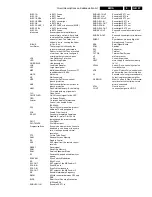
IN-SC1-G
In EXT1 Green
IN-SC1-R
In EXT1 Red
IN-SC1-SNDL
In EXT1 sound left
IN-SC1-SNDR
In EXT1 sound right
IN-SC2-B
In EXT2 Blue
IN-SC2-CVBS_Y
In EXT2 CVBS or luminance (SVHS)
IN-SC2-FBL
In EXT2 fast blanking
IN-SC2-G
In EXT2 Green
Interlaced
Scan mode where two fields are
used to form one frame. Each field
contains half the number of the total
amount of lines. The fields are
written in “pairs”, causing line flicker.
IO-BUS
In/Out - Bus
Last Status
The settings last chosen by the
customer and read and stored in
RAM or in the NVM. They are called
at start-up of the set to configure it
according the customers wishes
LDP
Line Deflection Protection
LED
Light Emitting Diode
LINE-DRIVE
Line drive signal
LNA
Low Noise Adapter
LSP
Large signal panel
MSP
Multistandard Sound Processor: ITT
sound decoder of EM1A
MUTE
Mute-Line
NC
Not Connected
NDF
No vertical DeFlection: vertical
flyback protection
NHF
No Horizontal deflection: horizontal
flyback protection
NVM
Non Volatile Memory: IC containing
TV related data e.g. alignments
O/C
Open Circuit
ON/OFF LED
On/Off control signal for the LED
OSD
On Screen Display
Painter
On screen display Teletext and
Control; also named Artistic
(SAA5800)
P50
Project 50 communication: protocol
between TV and peripherals
PCB
Printed Circuit board
PICNIC
Peripheral Integrated Combined
Network IC: main IC for 100 Hz
featuring and feature processing
PILOT
Pilot Signal
PILOTMUTE
Pilot Mute signal
Progressive Scan
Scan mode where all scan lines are
displayed in one frame at the same
time, creating a double vertical
resolution.
PTP
Picture Tube Panel
RAM
Random Access Memory
RC
Remote Control
RC5
RC5 signal from the remote control
receiver
RESET
Reset signal
ROM
Read Only Memory
SAM
Service Alignment Mode
SC
Sandcastle: pulse derived from sync
signals
SCAVEM
Scan Velocity Modulation
S/C
Short Circuit
SC1-OUT
EXT output of the MSP audio IC
SC2-B-IN
Scart2 Blue in
SC2-C-IN
Scart2 chrominance in
SC2-OUT
EXT output of the MSP audio IC
SIF
Sound Intermediate Frequency
SIMM
80-fold connector between LSP and
SSB
SLDP Smart
Local
Dooming
Prevention
(HW and SW)
SNDL-SC1-IN
Sound left EXT1 in
SNDL-SC1-OUT
Sound left EXT1 out
SNDL-SC2-IN
Sound left EXT2 in
SNDL-SC2-OUT
Sound left EXT2 out
SNDR-SC1-IN
Sound right EXT1 in
SNDR-SC1-OUT
Sound right EXT1 out
SNDR-SC2-IN
Sound right EXT2 out
SNDR-SC2-OUT
Sound right EXT2 out
SNDS-VL-OUT
Surround sound left variable level
out
SNDS-VR-OUT
Surround sound right variable level
out
SNERT
Synchronous No parity Eight bit
Reception and Transmit
SSB
Small Signal Board
STBY
Standby
SW
Subwoofer
TXT
Teletext
TXT DS
Teletext Dual Screen
µ
P
microprocessor
VA
Vertical Acquisition
VBAT
main supply for deflection (mostly
141 V)
VD100
Vertical Drive: vertical sync pulse
from deflection
VFB
Vertical Flyback Pulse: vertical sync
pulse coming from the feature box
VL
Variable Level out: processed audio
output towards external amplifier
WYSIWYR
What You See Is What You Record:
record selection that follows main
picture and sound
XTAL
Quartz crystal
Y-OUT
Luminance-signal to HOP IC


