Alignments
GB 78
EM1A
8.
Initial set-up
1.
Connect an external video pattern generator (PAL BG,
475.25 MHz) to the aerial input of the TV-set with a
crosshatch test pattern.
2.
Set 'Smart Picture' to NATURAL.
3.
Activate the SAM-menu (see chapter 5).
4.
Go to sub-menu GEOMETRY. Now the following
alignments can be performed:
Vertical slope (VER. SLOPE)
Align the vertical centre of the picture to the vertical centre of
the CRT.This is the first alignment to be performed of the
vertical alignments. For an easy alignment set SERV.BLK to
ON.
Service blanking (SERV. BLK)
Switch the blanking of the lower half of the screen ON/OFF
(to be used in combination with the vertical slope alignment).
Vertical amplitude alignment
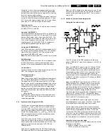
Align the vertical amplitude with potentiometer R3603 on the
LSP (see Fig. 8-1) so that the complete test pattern is visible.
Vertical shift alignment
Align the vertical centering with potentiometer R3609 on the
LSP (see Fig. 8-1) so that the test pattern is located vertically
in the middle. Repeat the 'vertical amplitude' alignment if
necessary.
Horizontal shift (HOR. SHIFT)
Align the horizontal centre of the picture to the horizontal
centre of the CRT.
Horizontal bow (HOR. BOW)
Align straight horizontal lines in the top and the bottom;
horizontal rotation around the centre.
Horizontal parallelogram (HOR. PARALLEL)
Align straight vertical lines in the top and the bottom; vertical
rotation around the centre.
East West width (EW. WIDTH)
Align the picture width until the complete test pattern is
visible.
East West parabola (EW. PARA)
Align straight vertical lines at the sides of the screen.
East West Trapezium (EW. TRAP)
Align straight vertical lines in the middle of the screen.
East West Upper Corner (EW. UCORN)
Align straight vertical lines in the upper corners of the screen.
East West Lower Corner (EW. LCORN)
Align straight vertical lines in the lower corners of the screen.
8.3.3
Tuner (Large Signal Panel and Double Window)
Note: Described alignments are only necessary when HIP or
NVM is changed.
IF PLL OFFSET
Supply, via a video generator (e.g. PM5518), a TV-signal
(e.g. colour bar) with a signal-strength of at least 1 mV and a
frequency of 471.25 MHz (use BG if possible, otherwise
match the system of your generator with the received signal
in the set).
Alignment procedure:
1.
Go to the 'Installation' menu.
2.
Select 'Manual installation'.
3.
Tune the TV-set to the system and frequency described
above via 'Search' - '471' - 'OK'.
4.
If the frequency showed in the line 'Fine tune' is between
471.18 MHz and 471.31 MHz, you don't need to re-adjust
the IF-AFC.
5.
If not, adjust the frequency in the 'Fine tune' line to
471.25 MHz and store the program by leaving the menu
(this is very important because this will disable the AFC
algorythm).
6.
Now go to the SAM and select 'Alignments' - 'General' -
'IF AFC'.
7.
First you must align the 'IF AFC'-parameter such that you
come into the AFC-window (AFA = 1)
8.
Then you must look for the point where the AFB-
parameter changes from 1 to 0. This level is the value
you are looking for.
9.
After adjustment store the value by returning to the
former menu.
10. Now return to the 'Installation' menu.
11. Select 'Manual Installation' - 'Search' - '47' - 'OK' and
store it. This will set the AFC 'on' again.
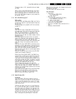
12. During the 'IF PLL'-parameter adjustment, one can see
feedback at the screen, by means of the 'AFA' and 'AFB'
indication (see table).
AGC
Set pattern generator (e.g. PM5418) to a colour bar video
signal and connect the RF output to aerial input. Set
amplitude to at least 1 mV and set frequency for PAL-BG to
471.25 MHz.
1.
Activate the SAM-menu. Go to the sub-menu TUNER,
and select the 'AGC' sub-menu.
2.
Connect a DC multi-meter to pin 1 of the tuner (item
1200 on LSP).
3.
Adjust the AGC until the voltage at pin 1 of the Tuner is
just below 3.8 V.
4.
The value can be incremented or decremented by
pressing the MENU LEFT/RIGHT button on the RC.
5.
Switch the set to STANDBY.
2ND AGC
Set pattern generator (e.g. PM5418) to a colour bar video
signal and connect the RF output to aerial input. Set
amplitude to at least 1 mV and set frequency for PAL-BG to
471.25 MHz.
1.
Activate the SAM-menu. Go to the sub-menu TUNER,
and select the '2nd AGC' sub-menu.
2.
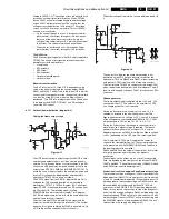
Connect a DC multi-meter to pin 1 of the tuner (7201 on
DW panel).
3.
Adjust the 2nd AGC until the voltage at pin 1 of the Tuner
is just below 3.8 V.
4.
The value can be incremented or decremented by
pressing the MENU LEFT/RIGHT button on the RC.
5.
Switch the set to STANDBY.
8.3.4
Black cut off
In the WHITE TONE sub menu, the values of the black cut off
level can be adjusted. The colour temperature mode
(NORMAL, DELTA COOL, DELTA WARM) or the colour (R,
G, B) can be selected with the UP/DOWN RIGHT/LEFT
cursor keys. The value can be changed with the RIGHT/
LEFT cursor keys.
First the values for the NORMAL colour temperature should
be selected. Then the offset values for the DELTA COOL and
DELTA WARM mode can be selected (note that the
alignment values are non-linear).
•
+1 to +63 represent a positive offset (63 is the maximum
positive offset).
AFA
AFB
IF-PLL offset
0
0
Decrease offset value
0
1
Increase off-set value
1
0
Correct
1
1
Correct

