Circuit descriptions and abbreviation list
GB 88
EM1A
9.
100 Hz conversion
The main task of the PICNIC is the conversion from 50 Hz to
100 Hz for YUV and HV-sync. In order to remove 'large area
flicker' (especially visible in a white picture), the field-rate of
the video is doubled by the FBX6. A 50 Hz frame frequency
is converted to 100 Hz. Also the line frequency (16 kHz) is
doubled (32 kHz). Basically, when the video input contains
fields A, B etc..., the conversion provides an AABB sequence
on the display. The actual conversion is done in the first Field
Memory by reading it twice at double speed, while writing it
once.
Automatic Aspect Ratio Adaptation (AARA)
This feature uses data from the 'black bar detection circuit' to
adapt the vertical and horizontal amplitude to an aspect ratio
belonging to the display without showing the black bars.
CTI
At CVBS video signals, the bandwidth of colour signals is
limited to 1/4 of the luminance bandwidth. Transients
between areas of different colours are therefore not very
sharp. The PICNIC can steepen these transients artificially
with a time manipulation algorithm.
Dynamic Contrast
To make the contrast (black/white) range wider, Philips has
invented Dynamic Contrast. It uses the digital memory used
in 100 Hz sets. It measures every A-field (25 x/s) and digitally
analyses where on the greyscale most of the image is
located. If it's a relatively dark image, the lighter part of that
image is stretched towards white, so that more contrast will
become visible in that picture. If it's a relatively light image,
the darker part of that image is stretched towards black, so
that these darker parts will have more contrast. When the
image is in the middle of the greyscale, both dark and light
parts are stretched.
PROZONIC
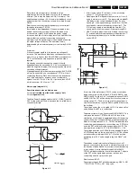
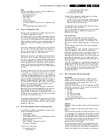
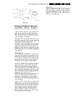
Figure 9-7
To the PICNIC external IC's are connected dependent of the
features.
If EM1A has only 100 Hz, then only one memory-IC is used
to store one frame.
For sets with Digital Scan the PROZONIC (IC7708,
SAA4990H) is added with two memory-ICs (IC7714 & 7715).
It is an abbreviation for PROgressive scan Zoom and Noise
reduction IC.
When applying this, the 2nd Field Memory has to be
installed. The following functions are available:
•
Line flicker reduction (Digital Scan): this is a feature to
reduce the 25 Hz interlace line flicker.
•
Dynamic Noise Reduction: noise affected signals can be
improved by combining the pixel values of the current
and past video fields. This is however only possible in
areas without movement.
•
Variable Vertical Sample Rate Conversion
•
Synchronous No Parity Eight bit Reception an
Transmission interface (SNERT-bus)
Depending on the chassis model, the FBX6 can have the
following specification:
9.1.8
Video: High-end Output Processor (HOP, diagram B4)
General
In the HOP (High-end Output Processor, TDA9330) the video
processor and digital deflection processor are integrated.
The main functions of the HOP are:
•
Video control (contrast, brightness, saturation, etc.).
•
2nd RGB interface for OSD/TXT.
•
Peak White Limiting.
•
Cut-off control and White Drive (RGB outputs).
•
Geometry control.
The YUV-signals from the PICNIC are fed to the HOP. In the
HOP, the video and geometry control parts are integrated.
Also the RGB-signals from TXT/OSD are inserted via the
HOP. This IC has all functions from a video processor and
geometry control (like the DDP in MD2). The geometry part
delivers the H-drive, EW-drive and also a drive signal for
rotation. The internal V-drive circuit of the HOP is not used (is
explained further on).
Video Control
After conversion to RGB again, the signals can be controlled
for Saturation, Contrast and Brightness.
2nd RGB interface for OSD/TXT
On pins 35 - 38 the RGB and fast blanking from the Painter
(OSD and TXT) are inserted.
Peak White Limiting
On pin 43 there is a Peak White Limiting signal line (PWL). If
the beam current (EHT-info line) increases, then the EHT-
info voltage will decrease. PWL is controlled by average
limiting via R3343/C2333.
Cut-off control
Switching the TV to Standby:
1.
Vertical scan is completed.
2.
Vertical flyback is completed (the horizontal output is
gated with the flyback pulse, so that the horizontal output
transistor cannot be switched on during the flyback
pulse).
3.
Slow stop of the horizontal output is started, by gradually
reducing the 'on' time at the horizontal output from
nominal to zero (this will take 50 ms).
4.
At the same time the fixed beam current is forced via the
black current loop for 25 ms. This is done by setting the
RGB outputs to a maximum voltage of 5.6 V.
In the EM1A a 'one-point' cut-off control is used:
A current of 8
µ
A (for cut-off) is fed to pin 44 of the HOP. This
is done with a measurement pulse during the frame flyback.
CL 96532156_017.eps
110100
BUS A
BUS
PICNIC/SAA4978H
DIGITAL SCAN
B
BUS
BUS C
BUS
BUS D
M
E
M
1
M
E
M
2
P
R
O
Z
N
I
C
I C
2
Y FEAT
Y DEC
U FEAT
U DEC
V FEAT
V DEC
HD100
HA
VD100
VA
BUS A
BUS
PICNIC/SAA4978H
100Hz CONFIGURATION
B
BUS
BUS C
BUS
BUS D
M
E
M
1
I C
2
Y FEAT
Y DEC
U FEAT
U DEC
V FEAT
V DEC
HD100
HA
VD100
VA
Featurebox 6 diversity
Set
Chipset
EM1A 1fH
N.A.
EM1A 2fH
1 Memory
EM1A 2fH DNR
1 Memory incl. DNR
EM1A 2fH Dig. Scan PR 2 Memories

