Circuit descriptions and abbreviation list
GB 94
EM1A
9.
Block Diagram
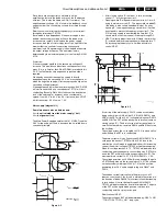
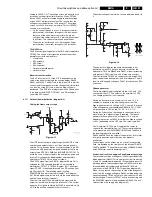
There is one configuration as shown below.
Figure 9-13
Circuit Description
IF & Video section
The TV uses one RF input to the DW’s tuner with a splitter.
The tuner on the main board receives RF from the splitter.
Due to this configuration, the main board tuner always
processes the Main picture while the DW tuner always
processes the Sub picture. If the picture between the two
tuners needs to be swapped, then the tuners’ RF frequencies
are swapped.
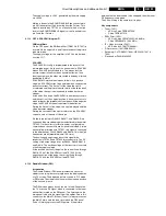
IF-TER from the tuner is fed to pin-1 & 2, IF circuits of
TDA888x IC7301 via a SAW filter. The AGC voltage for the
tuner can be adjusted in the SAM’s tuner menu.
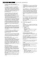
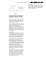
Dependant of the region execution, different SAW-filters are
applied.Therefore circuit diversity is unavoidable as shown in
figure below. The RESET-signal is used to set the SAW-filter
to different IF frequency modes. Table below shows IF
frequency settings by the RESET signal.
TUNER - 7201
SPLITTER
LA
T
AM & AP
RF to Main Tuner
1352
4
5
1
11
IF
+
+
RGB/
YUV
INPUT2
RGB/YUV
MATRIX
COLOUR
DECODING
SYNC
RBG/YUV
MATRIX
YUV INTERFACE
RGB
INPUT1
RGB
OUTPUT
DOUBLE WINDOW PROCESSOR
IC7801
SAB9081H
TDA888X
IC7301
7803
TDA8601
1333
4305
PIP-AUDIO
PIP-A
UDIO
12
11
10
6
7
8
8
12
10
10
6 8 9
2
3
4
4 3 1
0205
Y
-MAIN-OUT
U-MAIN-OUT
V
-MAIN-OUT
Y
-PIP+MAIN-IN
U-PIP+MAIN-IN
V
-PIP+MAIN-IN
98
2 100
40 45 46
83
79
81
56
49
87
72
SVSYNC
SHSYNC
D
VSYNC
DHSYNC
94
70
1
2
8
16
CVBS-PIP_TUN1-2-CVBS-IN
AP & LATAM
NAFTA & AP-NTSC
24
29
20
CVBS-SC1_AV1-IN
SEL_TUNER1
SEL_TUNER2
7402-B
7402-A
CVBS_TER_OUT
CVBS-SC2_AV2-IN
Y-CVBS-FRONT-IN
C-SC2_SVHS-IN
C-FRONT-IN
SEL-MAIN-R1R2
SEL-FRNT-RR
2
1
15
10
12
13
11
14
7401-B
7401-C
7401-A
12
13
14
11
2
1
15
5
3
4
41
42
43
R-SC1-IN_V
-IN
G-SC1-IN_Y
-IN
B-SC1-IN_U-IN
7402-C
4
5
3
7501
V-CHIP
SDA
SCL
14
15
7
SEL_PIP_CVBS
54
NAFTA ONLY
7403
IO
EXPANDER
4
5
6
7
9
10
11
12
3
2
SEL-MAIN-R1R2
SEL-FRNT-RR
SEL_TUNER1
SEL_TUNER2
FBLK
SEMI-STD-BY
SEL-YUV_RGB
RESET
GUIDE+
26
60
SDA
SCL
68
MY
MU
MV
SV
SU
SY
DV
DY
DU
CL 06532045_070.eps
010800


