Mechanical instructions
GB 11
EM1A
4.
4.
Mechanical instructions
4.1
Removing the Rear Cover
1.
Remove all the fixation screws of the rear cover.
2.
Now the rear cover can be removed by pulling it
backward.
4.2
Service positions
4.2.1
Service position LSP
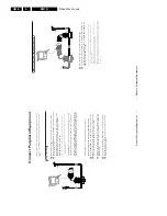
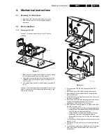
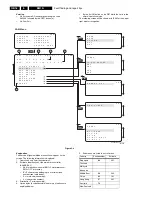
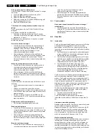
Position 1: For better accessibility of the LSP, do the
following:
Figure 4-1
1.
Remove the LSP-module from the bottom tray by pulling
the complete module back- and then upward.
2.
Hook the bracket in the first row of fixation holes of the
cabinet bottom. In other words reposition the bracket
from [1] to [2].
3.
The same can be done with the DW-module (position [3]
to [4]).
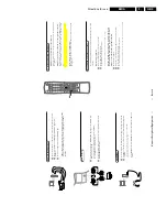
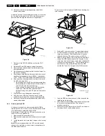
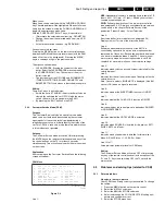
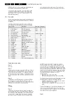
Position 2: This service position is comparable to that of the
A10A. To get access to the bottom side (solder side) of the
LSP, do the following:
Figure 4-2
1.
Disconnect the CRT/SCAVEM panel from the CRT-
socket.
2.
Release LSP and DW-module, and pull backward.
3.
Remove Mains switch module from bottomplate (see
description below).
4.
Free the necessary wiring from their fixation clamps, for
the ease of handling.
5.
Sometimes a cable must be disconnected for the ease of
handling, like the degaussing coil (0020) and
loudspeaker (1735, 1736 & 1737) cables.
6.
Now reposition following modules, in order to cope with
the LSP service position:
–
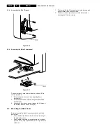
DAF-module from the LSP-bracket by pressing lever
while pushing the module forward in the direction of
the CRT (see also description below).
–
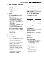
Mains Harmonic module from the LSP-bracket by
removing 1 screw and then slide the module
backward, away from the CRT (see also description
below).
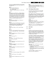
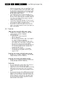
7.
Turn the chassis tray 90 degrees counter clockwise (see
figure 4.2 - [2]).
8.
Flip the chassis tray with the rear I/O panel towards the
CRT [3].
9.
Place the hook of the tray in the fixation hole at the right
side of the cabinet bottom and pull the chassis tray
backward [4].
CL 06532130_004.eps
031000
Bottom tray
2
1
2
1
4
3
LSP - bracket
SSB
LSP
A
CL 06532130_006.eps
121000
B
2
1
4
3


