


Programming Your Application
6-39
590 Series DC Digital Converter
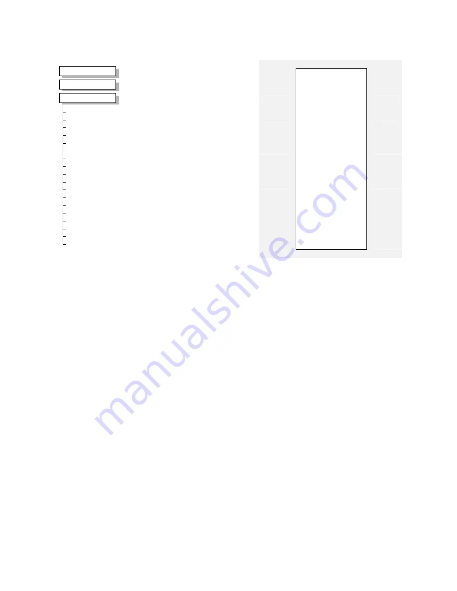
PID
This is a general purpose PID block which
can be used for many different closed loop
control applications. The PID feedback can
be loadcell tension, dancer position or any
other transducer feedback such as pressure,
flow etc.
Features:
•
Independent adjustment of gain and
time constants.
•
Additional first-order filter (F).
•
Functions P, PI, PD, PID with/without
F individually selected.
•
Ratio and divider for scaling each
input.
•
Independent positive and negative
limits.
•
Output scaler (Trim).
•
Gain profiled by diameter for centre-
driven winder control.
PID
–
PID OUTPUT [417]
–
0.00%
–
PID CLAMPED [416]
–
FALSE
–
PID ERROR [415]
–
0.00%
1.0
–
[404] PROP. GAIN
–
5.00s
–
[402] INT. TIME CONST.
–
0.000s
–
[401] DERIVATIVE TC
–
100.00%
–
[405] POSITIVE LIMIT
–
-100.00%
–
[406] NEGATIVE LIMIT
–
0.2000
–
[407] O/P SCALER (TRIM)
–
0.00%
–
[410] INPUT 1
–
0.00%
–
[411] INPUT 2
–
1.0000
–
[412] RATIO 1
–
1.0000
–
[413] RATIO 2
–
1.0000
–
[418] DIVIDER 1
–
1.0000
–
[414] DIVIDER 2
–
ENABLED
–
[408] ENABLE
–
OFF
–
[409] INT. DEFEAT
–
0.100s
–
[403] FILTER T.C.
–
0
–
[473] MODE
–
20.00%
–
[474] MIN PROFILE GAIN
–
–
PROFILED GAIN [475]
–
0.0
MMI Menu Map
1
SETUP PARAMETERS
2
SPECIAL BLOCKS
3
PID
PROP.
GAIN
INT. TIME CONST.
DERIVATIVE
TC
POSITIVE
LIMIT
NEGATIVE
LIMIT
O/P SCALER (TRIM)
INPUT
1
INPUT
2
RATIO
1
RATIO
2
DIVIDER
1
DIVIDER
2
ENABLE
INT.
DEFEAT
FILTER
T.C.
MODE
MIN PROFILE GAIN
PROFILED
GAIN
Parameter Descriptions
PROP. GAIN
Range: 0.0 to 100.0
This is a pure gain factor which shifts up or down the whole Bode PID transfer function leaving
the time constants unaffected. A value of P = 10.0 means that, for an error of 5%, the
proportional part (initial step) of the PID output will be:
10 x [ 1 + (Td/Ti) ] x 5 % , i.e. approx. 50% for Td << Ti.
INT. TIME CONST.
Range: 1.000s to 10.000s
The integrator time constant (Ti)
DERIVATIVE TC
Range: 0.000s to 10.000s
The differentiator time constant (Td). When Td = 0 the transfer function of the block becomes a
P+I.
POSITIVE LIMIT
Range: 0.00% to 105.00%
The upper limit of the PID algorithm.
NEGATIVE LIMIT
Range: -105.00% to 0.00%
The lower limit of the PID algorithm.
O/P SCALER (TRIM)
Range: -3.0000 to 3.0000
The ratio which the limited PID output is multiplied by in order to give the final PID Output.
Normally this ratio would be between 0 and 1.
INPUT 1
Range: -300.00% to 300.00%
This can be either a position/tension feedback or a reference/offset.
INPUT 2
Range: -300.00% to 300.00%
This can be either a position/tension feedback or a reference/offset
RATIO 1
Range: -3.0000 to 3.0000
This multiplies Input 1 by a factor (Ratio 1).
RATIO 2
Range: -3.0000 to 3.0000
This multiplies Input 2 by a factor (Ratio 2).
Summary of Contents for 590 series
Page 12: ...605 Frequency Inverter HA389591 Issue 1 Contents Contents Page Cont 12...
Page 16: ...1 4 Getting Started 590 Series Digital Converter...
Page 22: ...2 6...
Page 64: ...3 42 Installing the Converter 590D DC Digital Converter HA467078...
Page 82: ...4 18 Operating the Converter 590 Series DC Digital Converter...
Page 90: ...5 8 The Man Machine Interface MMI 590 Series DC Digital Converter...
Page 168: ...9 6 Control Loops 590 Series DC Digital Converter...
Page 222: ...13 14 Standard and Optional Equipment 590 Series DC Digital Converter...
Page 234: ...15 2 The Default Application 590 Series DC Digital Converter...
Page 242: ......


