


Installing the Converter
3-11
590D DC Digital Converter - HA467078
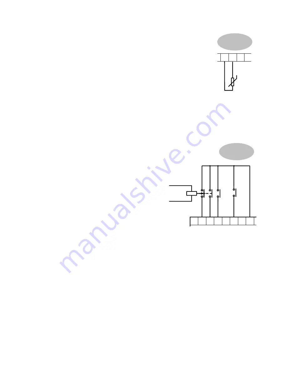
Thermistor (C1, C2)
The motor temperature alarm (THERMISTOR) cannot be inhibited
in software. Terminals C1 and C2 must be linked if sensors are not
fitted.
We recommend that you protect the dc motor against overtemperature by
the use of temperature sensitive resistors or switches in the field and
interpole windings of the machine.
If the motor is fitted with over-temperature sensing devices such as
thermostats, microtherms or PTC thermistors, these should be connected
(in series) between terminals C1 and C2. Thermistors must have a
combined working resistance of 200 Ohms or less, rising to 2000 Ohms at
over-temperature. These thermistors are classified by IEC34-II as Mark
A.
•
Temperature sensitive resistors have a low resistance (typically 100 Ohms) up to a reference
temperature (typically 125
°
C), above this the resistance rises rapidly to greater than 2000
Ohms. The controller’s thermistor alarm will activate at 1800 Ohms.
Temperature switches are usually normally closed, and open at approximately 105
°
C. The
thermistor alarm is latched in software and must be reset by re-starting the Converter.
Enable, Start/Run, Emergency Stop Relay (B8, B9, C3, C5, C9)
Terminal C5 (Enable) must be connected to Terminal C9 (+24V) in
order to allow the drive to run.
Start
The basic run/start sequence of the controller
is provided by Terminal C3 (Start/Run),
although other safeguards for extra protection
are provided by Terminal B8 (Program Stop)
and Terminal B9 (Coast Stop).
Assuming that the Program Stop and Coast
Stop terminals are held TRUE, then a single
contact connected between Terminal C9
(+24V) and Terminal C3 (Start/Run) when
closed will cause the controller to energise
the Main Contactor and, provided Terminal
C5 (Enable) is also TRUE, will run the
associated DC motor.
When the single contact to Terminal C3 (Start/Run) is opened, the controller will decelerate the
motor to zero speed at a rate determined by the STOP TIME parameter’s value and the MAIN
CURR. LIMIT value. Refer to Chapter 6: “Application Programming” - STOP RATES for
further information.
Note:
The Enable input is useful to inhibit the drive without opening the main contactor,
however, it is not a safe mode of operation as the drive dc output is only reduced to
zero. If the equipment controlled by the drive is to be serviced, then this method should
be avoided and the drive disabled and isolated.
A regenerative drive can be stopped using a
Normal Stop
, a
Program Stop,
or an
Emergency Stop,
as described below
.
However, a non-regenerative drive can only be made
to stop faster than friction and loading will allow by Dynamic Braking.
Normal Stop
If the +24V is removed from Terminal C3 whilst the drive is controlling the motor under "Run"
conditions, the controller will cause the motor to decelerate rapidly to rest at a rate determined
by STOP LIMIT, STOP TIME and CURR. LIMIT.
Program Stop
8
MINIMUM
CONNECTION
REQUIREMENT
C1
C2
F1
G4
THERMISTOR
9
MINIMUM
CONNECTION
REQUIREMENT
EMERGENCY
STOP
RELAY
START
/RUN
ENABLE
B9
A1
B8
C5
C3
C9
Summary of Contents for 590 series
Page 12: ...605 Frequency Inverter HA389591 Issue 1 Contents Contents Page Cont 12...
Page 16: ...1 4 Getting Started 590 Series Digital Converter...
Page 22: ...2 6...
Page 64: ...3 42 Installing the Converter 590D DC Digital Converter HA467078...
Page 82: ...4 18 Operating the Converter 590 Series DC Digital Converter...
Page 90: ...5 8 The Man Machine Interface MMI 590 Series DC Digital Converter...
Page 168: ...9 6 Control Loops 590 Series DC Digital Converter...
Page 222: ...13 14 Standard and Optional Equipment 590 Series DC Digital Converter...
Page 234: ...15 2 The Default Application 590 Series DC Digital Converter...
Page 242: ......


