


3-14
Installing the Converter
590D DC Digital Converter - HA467078
Motor Field Connections
The FIELD CONTROL function block controls the motor field. The FLD CTRL MODE IS
parameter allows you to select either Voltage or Current Control mode.
•
In Voltage Control mode, the RATIO OUT/IN parameter is used to scale the motor field
output voltage as a percentage of the input supply voltage.
•
In Current Control mode, the SETPOINT parameter is used to set an absolute motor field
output current, expressed as a percentage of the calibrated field current (IF CAL).
Internal/External Supply
The internal motor field is more widely used, however, there is provision on the Control Board
for an external motor field supply to be connected (perhaps for where the field voltage is greater
than the input voltage and therefore not attainable, or where the motor field is switched
separately for convenience).
Note:
For information about the following power boards refer to Chapter 11: “Technical
Specifications” - Power Board Types, and Terminal Information (Power Board).
Power Board - PCB Reference 385851
This power board (printed with the above number) can be altered for use with either an internal
or external motor field supply:
Internal Motor Field (default for this board)
Terminals D3 and D4, the motor field outputs, are energised when the 3-phase supply to
L1/L2/L3 is energised and the internal motor field is used. Terminals D1 and D2 are not
energised. The internal motor field supply is fused by the 10A fuses, FS2 & FS3.
External Motor Field Connections
Terminals D1 and D2 on the Power Board
can be used for an external ac supply
connection for the Motor Field Supply.
A simple re-wiring procedure disconnects
the internal motor field supply and prepares
terminals D1 and D2 for the external ac
supply connection.
You should provide suitably rated external,
fast-acting semi-conductor fusing, to a
maximum of 10A.
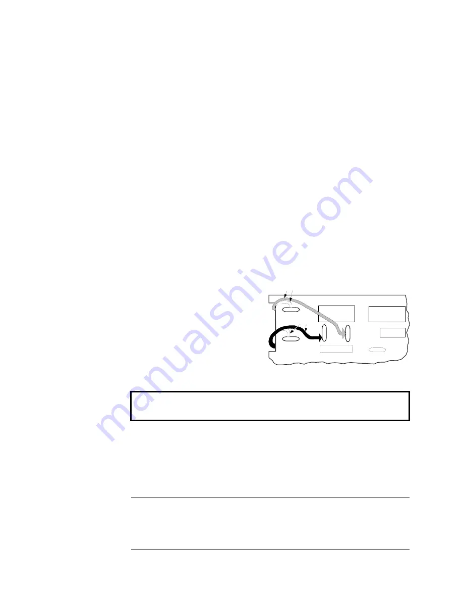
Re-Wiring Procedure
WARNING!
Isolate the drive.
1.
Loosen the control board fixing screws (2 off) and position the control board to allow access
to the power board.
2.
Remove the
red
link from the Faston connector “F16” on the left-hand side of the board and
connect it to staging post “F19”, located below terminal D1.
3.
Remove the
yellow
link wire from the Faston connector
“
F8” on the left-hand side of the
board and connect it to staging post
“
F18”, located below terminal D2.
Caution
When using an external ac input it is important to have the correct phase relationship on
the terminals. The supply must be derived from L1 (Red) and L2 (Yellow) phases directly
or indirectly through a transformer.
L1 must be connected to D1, and L2 connected to D2.
The external field supply can now be connected and power restored to the drive.
POWER BOARD AH385851
D1
D2
D3
D4
Red
F8
F16
Yellow
F18
F19
Summary of Contents for 590 series
Page 12: ...605 Frequency Inverter HA389591 Issue 1 Contents Contents Page Cont 12...
Page 16: ...1 4 Getting Started 590 Series Digital Converter...
Page 22: ...2 6...
Page 64: ...3 42 Installing the Converter 590D DC Digital Converter HA467078...
Page 82: ...4 18 Operating the Converter 590 Series DC Digital Converter...
Page 90: ...5 8 The Man Machine Interface MMI 590 Series DC Digital Converter...
Page 168: ...9 6 Control Loops 590 Series DC Digital Converter...
Page 222: ...13 14 Standard and Optional Equipment 590 Series DC Digital Converter...
Page 234: ...15 2 The Default Application 590 Series DC Digital Converter...
Page 242: ......


