203
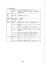
Screen Description
RRP Domain
Name
Displays the domain name.
Node Type
Displays the node role.
Master
Displays that the Switching Hub controls the ring
operation.
Each domain has only one master node.
Transit
Displays that the Switching Hub is not a master node.
Ring Status
Displays the ring status.
IDLE
Displays that the Ring Redundant Protocol function is
disabled.
Complete
Displays that a ring topology has been correctly
established.
This status is displayed for the master nodes only.
Failed
Displays that a ring topology has not been established.
This status is displayed for the master nodes only.
Link-Up
Displays that a ring topology has been correctly
established.
This status is displayed for the transit nodes only.
Link-Down
Displays that a ring topology has not been established.
This status is displayed for the transit nodes only.
Pre-Forward
ing
Displays that a ring topology is being established.
This status is displayed for the transit nodes only.
Primary Port
Displays the primary port.
Primary Port
Status
Displays the primary port status.
Unknown
Displays that the domain is invalid.
Fowarding
Displays normal communication status.
Down
Displays that the port does not link up.
Blocking
Displays that no frames other than control frames are
not received.
Primary Port
Role
Displays the primary port role.
Upstream
Operating as an upstream port
Downstrea
m
Operating as a downstream port
Secondory Port Displays the secondary port.
Secondory Port
Status
Displays the secondary port status.
Unknown
Displays that the domain is invalid.
Fowarding
Displays normal communication status.
Down
Displays that the port does not link up.
Blocking
Displays that no frames other than control frames are
not received.
Secondory Port
Role
Displays the secondary port role.
Upstream
Operating as an upstream port
Downstrea
m
Operating as a downstream port
Polling Interval Displays the polling interval.
Fail Period
Displays the timeout for polling.
Ctrl VLAN
Displays the set control VLAN ID.
Data VLAN(s)
Displays the set data VLAN ID.
Summary of Contents for Switch-M12PWR
Page 17: ...17 Fig 2 2 Mounting to Wall ...
Page 20: ...20 function does not work Therefore use a cross cable to connect them ...
Page 30: ...30 ...
Page 36: ...36 ...
Page 49: ...49 ...
Page 69: ...69 ...
Page 81: ...81 setting and the management VLAN status of VLAN ID 1 is UP ...
Page 96: ...96 Press S Q Return to the previous menu ...
Page 98: ...98 ...
Page 122: ...122 Q Return to the previous menu ...
Page 125: ...125 ...
Page 130: ...130 ICMP Type Displays the ICMP type ...
Page 156: ...156 Threshold Displays the threshold of the number of packets per second ...
Page 173: ...173 Fig 4 7 49 Display of values accumulated after resetting the counters ...
Page 185: ...185 Q Return to the previous menu ...
Page 211: ...211 Q Return to the previous menu ...
Page 232: ...232 IEEE8021 PAE MIB IEEE802 1X IEEE8023 LAG MIB IEEE 802 3ad ...
Page 237: ...237 IEEE 802 3af standard ...
Page 240: ...240 P0813 1084 ...

