18
2
2
.
.
3
3
.
.
M
M
o
o
u
u
n
n
t
t
i
i
n
n
g
g
t
t
o
o
S
S
t
t
e
e
e
e
l
l
P
P
r
r
o
o
d
d
u
u
c
c
t
t
Take out the supplied four rubber feet and four magnets, and place this
Switching Hub upside down.
Attach the rubber feet to dents located at the corners of the bottom face,
and fix the magnets firmly with the supplied four screws (for magnet
mount).
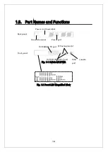
Fig. 2-3 Bottom Face
Note: Do not install the switch in such places as the unstable location,
where there is strong vibration or shock, or where a person may walk
under this Switching Hub.
Deviation could lead to injury or equipment failure.
Rubber foot
Rubber foot
Summary of Contents for Switch-M12PWR
Page 17: ...17 Fig 2 2 Mounting to Wall ...
Page 20: ...20 function does not work Therefore use a cross cable to connect them ...
Page 30: ...30 ...
Page 36: ...36 ...
Page 49: ...49 ...
Page 69: ...69 ...
Page 81: ...81 setting and the management VLAN status of VLAN ID 1 is UP ...
Page 96: ...96 Press S Q Return to the previous menu ...
Page 98: ...98 ...
Page 122: ...122 Q Return to the previous menu ...
Page 125: ...125 ...
Page 130: ...130 ICMP Type Displays the ICMP type ...
Page 156: ...156 Threshold Displays the threshold of the number of packets per second ...
Page 173: ...173 Fig 4 7 49 Display of values accumulated after resetting the counters ...
Page 185: ...185 Q Return to the previous menu ...
Page 211: ...211 Q Return to the previous menu ...
Page 232: ...232 IEEE8021 PAE MIB IEEE802 1X IEEE8023 LAG MIB IEEE 802 3ad ...
Page 237: ...237 IEEE 802 3af standard ...
Page 240: ...240 P0813 1084 ...


