24
4
4
.
.
2
2
.
.
L
L
o
o
g
g
i
i
n
n
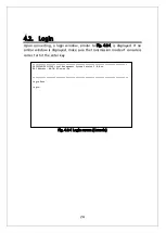
Upon connecting, a login window, similar to Fig. 4-2-1, is displayed. If no
similar window is displayed, make sure the transmission mode of console is
correct or hit the enter key.
Fig.
4-2-1 Login screen (Console)
=============================================================================
PN23129K/PN23129A Local Management System Version 2.0.0.xx
MAC Address: 00:C0:8F:xx:xx:xx
==============================================================================
Login Menu
Login:
Summary of Contents for Switch-M12PWR
Page 17: ...17 Fig 2 2 Mounting to Wall ...
Page 20: ...20 function does not work Therefore use a cross cable to connect them ...
Page 30: ...30 ...
Page 36: ...36 ...
Page 49: ...49 ...
Page 69: ...69 ...
Page 81: ...81 setting and the management VLAN status of VLAN ID 1 is UP ...
Page 96: ...96 Press S Q Return to the previous menu ...
Page 98: ...98 ...
Page 122: ...122 Q Return to the previous menu ...
Page 125: ...125 ...
Page 130: ...130 ICMP Type Displays the ICMP type ...
Page 156: ...156 Threshold Displays the threshold of the number of packets per second ...
Page 173: ...173 Fig 4 7 49 Display of values accumulated after resetting the counters ...
Page 185: ...185 Q Return to the previous menu ...
Page 211: ...211 Q Return to the previous menu ...
Page 232: ...232 IEEE8021 PAE MIB IEEE802 1X IEEE8023 LAG MIB IEEE 802 3ad ...
Page 237: ...237 IEEE 802 3af standard ...
Page 240: ...240 P0813 1084 ...

