32
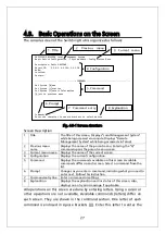
Screen Description
System up for Displays the cumulative time since the power on of this Switching Hub.
Boot /
Runtime Code
Version
Displays this Switching Hub's firmware version.
The left side displays the Boot Code and the right side displays the
Runtime Code.
("TFTP Software Upgrade" in 4.9.1 is about Runtime Code update.)
Hardware
Information
Displays the hardware information.
Version
Displays the hardware version information.
CPU
Utilization
Displays the CPU utilization.
DRAM / Flash
Size
Displays the sizes of installed DRAM and FLASH
memory.
DRAM User
Area Size
Displays the sizes of the user area memory and unused
memory.
System
Temperature
Displays the internal temperatures of the Switching
Hub.
The sensors measure the temperature of CPU and
system.
Administration
Information
Items shown here are configured in accordance with "4.6.1 System
Administration Configuration."
Switch Name
Displays the Switching Hub name. The factory default
setting is blank. For configuration details, refer to 4.6.1.
Switch
Location
Displays the Switching Hub's location. The factory
default setting is blank. For configuration details, refer
to 4.6.1.
Switch
Contact
Displays the contact information. The factory default
setting is blank. For configuration details, refer to 4.6.1.
System
Address
Information
Items shown here are configured in accordance with "4.6.2 System IP
Configuration."
MAC Address
Displays the MAC address of this Switching Hub. This
value is uniquely assigned to each device and cannot be
changed.
IP Address
Displays the Switching Hub's current IP address. 0.0.0.0
is the factory default setting. For configuration details,
refer to 4.6.2.
Subnet Mask
Displays the Switching Hub's current subnet mask.
0.0.0.0 is the factory default setting. For configuration
details, refer to 4.6.2.
Default
Gateway
Displays the IP address of the router for the default
gateway. 0.0.0.0 is the factory default setting. For
configuration details, refer to 4.6.2.
DHCP Mode:
Displays whether to get an IP address using DHCP. For
configuration details, refer to 4.6.2.
Summary of Contents for Switch-M12PWR
Page 17: ...17 Fig 2 2 Mounting to Wall ...
Page 20: ...20 function does not work Therefore use a cross cable to connect them ...
Page 30: ...30 ...
Page 36: ...36 ...
Page 49: ...49 ...
Page 69: ...69 ...
Page 81: ...81 setting and the management VLAN status of VLAN ID 1 is UP ...
Page 96: ...96 Press S Q Return to the previous menu ...
Page 98: ...98 ...
Page 122: ...122 Q Return to the previous menu ...
Page 125: ...125 ...
Page 130: ...130 ICMP Type Displays the ICMP type ...
Page 156: ...156 Threshold Displays the threshold of the number of packets per second ...
Page 173: ...173 Fig 4 7 49 Display of values accumulated after resetting the counters ...
Page 185: ...185 Q Return to the previous menu ...
Page 211: ...211 Q Return to the previous menu ...
Page 232: ...232 IEEE8021 PAE MIB IEEE802 1X IEEE8023 LAG MIB IEEE 802 3ad ...
Page 237: ...237 IEEE 802 3af standard ...
Page 240: ...240 P0813 1084 ...


