


The contents of these instructions are divided into major Sections, as follows:
1.0
Introduction
2.0
About These Instructions
3.0
Contents of the Painless Wire Harness Kit
4.0
Tools Needed
5.0
Pre-Installation and General Guidelines
6.0
Wire Harness Physical Installation Instructions
7.0
General Electrical Systems – All Jeeps
8.0
Charging and Ignition Systems - As Originally Manufactured by Jeep
9.0
Charging and Ignition Systems - Jeeps with GM Engines Installed
10.0
Charging and Ignition Systems - Jeeps with Ford Engines Installed
11.0
Charging and Ignition Systems - Jeeps with Mopar Engines Installed
12.0
Wire Connection Index and Fuse Requirements
The Sections are further divided into Paragraphs and Steps. Throughout, the Figure
numbers refer to illustrations and the Table numbers refer to information in table form. These
are located in the back of this manual. Always pay special and careful attention to the
Notes
,
especially those in Tables, and ANY text marked CAUTION.
Note:
Painless Performance has elected to use GM wire color codes
throughout this manual. Jeep has changed color codes too many times
to make complete and accurate documentation practicable. Painless
regrets any inconvenience this may cause.
3.0
CONTENTS OF THE PAINLESS WIRE HARNESS KIT
Refer to Figure 3.1 to take an inventory to see that you have everything you are supposed to
have in this kit. If anything is missing, go the dealer where you obtained this kit or contact
Painless Performance at 800-423-9696. The Painless Wire Harness Kit should contain the
following items:
▪
The main harness, with the fuse block wired in and fused installed.
▪
2 Headlamp Connector Cables
▪
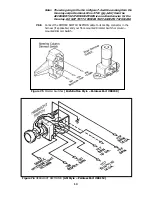
Alternator Bag w/ MIDI-Fuse Assembly (Painless Part #80000) (See Figure 8.3)
▪
Firewall Grommet (large) for 1974 and earlier.
▪
2 Fender Well Grommets (for Headlamps)
▪
2 Packages of Nylon Tie Wraps.
▪
2 Turn Signal Connectors (if applicable) for ’75 and later.
▪
Parts Box, containing a GM Alternator Connector, Terminals, Splices, etc.
▪
P/N 90504 Painless Wiring Manual (this booklet).
2
Summary of Contents for 10106
Page 29: ...Figure 8 8 Ford Ignition Diagram Duraspark II Systems Figure 8 11 Ford Switch Connectors 24...
Page 40: ...Diagram 1 Engine Wiring Diagram 35...
Page 41: ...Diagram 2 Instrument Panel Section Wiring Diagram 35...
Page 42: ...Diagram 3 Integrated Brake Lights Separate Turn Brake Lights 36...
Page 44: ......