


CAUTION:
BOTH AMMETER TERMINALS MUST BE ABSOLUTELY ISOLATED FROM
GROUND. IF EITHER AMMETER TERMINAL COMES IN CONTACT WITH
GROUND A HARNESS FIRE IS INEVITABLE. USE EXTREME CARE AND
DILIGENCE IN CONNECTING AMMETERS.
BE SURE YOUR AMMETER’S CURRENT (AMPS) RATING EXCEEDS THE CURRENT
OUTPUT OF YOUR ALTERNATOR. PERFECT PERFORMANCE PRODUCTS, INC.
DOES NOT RECOMMEND USING ANY AMMETER RATED AT LESS THAN 65
AMPS. DO NOT USE AN AMMETER WITH ANY HIGH-OUTPUT ALTERNATOR
(MORE THAN 65 AMPS). WE SUGGEST USING A VOLT METER INSTEAD.
7.4
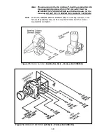
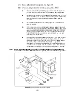
Steering Column Wiring – Turn Signal & Ignition Switch Connectors. See
Figure 7.2 and Table 7.1.
7.4.1 There are two different plugs on most tilt columns. The difference is in the
length of the male plug that is mounted ON THE COLUMN. One plug is 3-7/8”
(3.875”) long and the other is 4-1/4" (4.250"). This is only a difference of 3/8"
(0.375"), so measure the plug carefully. The Wire Harness Kit has included two
different female connectors to mate with the column-mounted plug. See Figure
7-2 to determine which female connector is correct for your automobile.
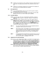
The TURN SIGNAL SECTION wires may have already been terminated for you. If
not cut wires to length and install terminals provided. Choose the proper plug
and install the terminals according to Table 7-1, as shown in Figure 7-2. The
GM wire color codes have been included for reference.
Note: The terminals will only insert into the connector ONE WAY, as shown in
Figure 7-2. Make certain you are inserting the wire into the CORRECT
LOCATION as the terminals are difficult if not impossible to remove
once inserted
.
7.4.2
The Steering Column Wiring comes with GM ignition switch connectors pre-
wired. See Table 7-1 and Figure 7-2 for color codes, wire numbers, and wire
designations for the Ignition Switch Connectors.
Figure 7.2 GM Turn Signal Connectors
9
Summary of Contents for 10106
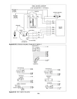
Page 29: ...Figure 8 8 Ford Ignition Diagram Duraspark II Systems Figure 8 11 Ford Switch Connectors 24...
Page 40: ...Diagram 1 Engine Wiring Diagram 35...
Page 41: ...Diagram 2 Instrument Panel Section Wiring Diagram 35...
Page 42: ...Diagram 3 Integrated Brake Lights Separate Turn Brake Lights 36...
Page 44: ......