13.0
Testing the System……………………………………………………………………………………………….…..30
12.0
Wire Connection Index and Fuse Requirements……..……………………………………………….……30
12.1
Wire Connection Index…………………………….………………………………………………….…31
12.2
Fuse Requirements……………………………………………………………………………………………..…... 34
List of Figures
3.1
The Painless Wire Harness Kit………………………………………………………….
3
6.1
MIDI-Fuse……………………………………………………………………………………... 7
7.1
Ammeter & MIDI-Fuse…………………………………………………………………….. 8
7.2
GM Turn Signal Connectors……………………………………………………………… 9
7.3
Interior Lighting……………………………………………………………………………..
10
7.4
HEADLIGHT SECTION A………………………………………………………………….
12
7.5
Dimmer Switches……………………………………………………………………………
13
7.6
HEADLIGHT SECTION B………………………………………………………………….
13
7.7
Painless Fan Relay Kit……………………………………………………………………..
14
8.1
Generator Charging System…………………………………………………………….
16
8.2
Motorola Alternator Charging System……………………………………………….
17
8.3
Motorcraft Alternator Charging System (2 configurations)…………………..
18
8.4
Delco Alternator Charging System (Internal Regulator)………………………
19
8.5
Delco Ignition (Start/Run) System……………………………………………………. 20
8.6
Prestolite BID Ignition (Start/Run) System………………………………………..
21
8.7
Motorcraft Electronic Ignition (Start/Run) System………………………………
23
8.8
Ford Ignition Diagram (Duraspark II Systems)………………………………….. 24
8.9
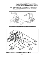
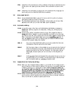
Ford Ignition Switch Connectors………………………………………………………. 24
9.1
Delco Alternator Charging System (External Regulator)………………………
25
10.1 Ford Ignition (Start/Run) System……………………………………………………..
26
11.1 Mopar Alternator Charging System…………………………………………………..
27
11.2 Mopar Ignition (Start/Run) System…………………………………………………..
29
List of Tables
7.1
Keyed-Column Ignition and Turn Signal Wiring………………………………….. 10
7.2
Mopar Ignition & Turn Signal Wiring #1……………………………………………. 11
7.3
Mopar Ignition & Turn Signal Wiring #2……………………………………………. 11
12.1 Wire Connection Index, 1 of 3….………………………………………………………. 31
12.1 Wire Connection Index, 2 of 3………………………………………………………….. 32
12.1 Wire Connection Index, 3 of 3………………………………………………………….. 33
12.2 Fuse Requirements…………………………………………………………………………. 34
List of Diagrams
Diagram 1 Engine Wiring………………………………………………………………………. 35
Diagram 2 Instrument Panel Section Wiring…………………………………………….
36
Diagram 3 Integrated Brake Lights & Separate Turn/Brake Lights……………..
37
ii
Summary of Contents for 10106
Page 29: ...Figure 8 8 Ford Ignition Diagram Duraspark II Systems Figure 8 11 Ford Switch Connectors 24...
Page 40: ...Diagram 1 Engine Wiring Diagram 35...
Page 41: ...Diagram 2 Instrument Panel Section Wiring Diagram 35...
Page 42: ...Diagram 3 Integrated Brake Lights Separate Turn Brake Lights 36...
Page 44: ......


