7.4.3
IGNITION SWITCH SECTION wire #719 (pur) has been cut and spade
lugs installed on the GM keyed steering column wiring. These spade
lugs are to be connected to the Neutral Safety Switch at the base of the
steering column. If using a neutral safety switch on a floor shifter or in
the transmission, the two purple wires with the yellow spade lugs must
be connected together and the (pur) #719 needs to be routed to the
neutral safety switch, cut and connected to it, then continued on to the
starter solenoid.
7.4.4
The harness does not support seat belt buzzers or key alarms.
NOTE: To supply power to a throttle body or tuned port fuel injection use
ENGINE SECTION A wire #720 (pnk) as the fused ignition power
source.
Table 7.1 Keyed-Column Ignition and Turn Signal Wiring
Figure 7.3 Interior Lighting
10
TURN SIGNAL SECTION
GM
Designation
Painless
Painless
Turn Signal
Color
Wire #
Color
Connector
Blk
Horn
753
Blk
G
LtBlu
LF Turn Signal
726
LtBlu
H
DkBlu
RF Turn Signal
725
Blu
J
Brn
Hazard Flasher
751
Brn
K
Pur
Turn Flasher
752
Pur
L
Ylw
LR Turn Signal
749
Ylw
M
Grn
RR Turn Signal
748
Grn
N
Wht
Stop Lamp Switch
718
Wht
P
IGNITION SWITCH SECTION
Pur/Wht
Ignition Start
719
Pur
Pnk
Ignition Coil
731
Pnk
Orn
Ignition Switched B+
733
Orn
Red
Battery B+
734
Red
Brn
Ignition Accessory
732
Brn
Summary of Contents for 10106
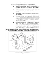
Page 29: ...Figure 8 8 Ford Ignition Diagram Duraspark II Systems Figure 8 11 Ford Switch Connectors 24...
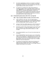
Page 40: ...Diagram 1 Engine Wiring Diagram 35...
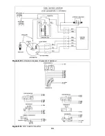
Page 41: ...Diagram 2 Instrument Panel Section Wiring Diagram 35...
Page 42: ...Diagram 3 Integrated Brake Lights Separate Turn Brake Lights 36...
Page 44: ......


