


8.2.2
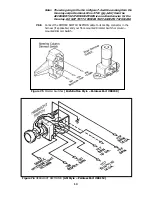
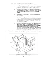
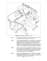
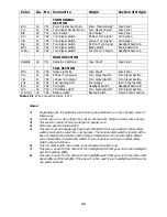
Delco Alternator – Internal Regulator. See Figure 8.4.
A.
Connect ENGINE SECTION wire #714 (wht) to Alternator terminal 1.
Connect ENGINE SECTION wire #795 (red) to Alternator terminal 2
Connect one end of the supplied large 6 gauge red wire to the Alternator
Output lug (Bat).
B.
A connector and terminals for late GM Alternators are included in the
alternator bag.
C.
If engine run on occurs after the ignition is turned off, the provided
diode in the alternator bag will need to be installed. Instructions can be
found in the illustration below.
Figure 8.4 Delco Alternator (Internal Regulator)
8.2.3
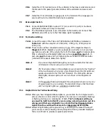
Delco One-Wire Alternator
A.
Connect the supplied large 6 gauge red wireto the Alternator Output lug
(Bat).
B.
Insulate and stow ENGINE SECTION wire #714 (wht) and #795 (red)
C.
When using a 1-wire alternator you must use a voltmeter or ammeter. A
warning light cannot be wired in.
19
Summary of Contents for 10106
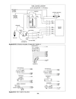
Page 29: ...Figure 8 8 Ford Ignition Diagram Duraspark II Systems Figure 8 11 Ford Switch Connectors 24...
Page 40: ...Diagram 1 Engine Wiring Diagram 35...
Page 41: ...Diagram 2 Instrument Panel Section Wiring Diagram 35...
Page 42: ...Diagram 3 Integrated Brake Lights Separate Turn Brake Lights 36...
Page 44: ......