7.5
Interior Lighting. See Figure 7.3.
7.5.1
Interior Lights are switched through the door switches and the dash-mounted
headlight switch, which is usually rotated counter-clockwise to turn on. These
switches apply ground to the circuit. YOU WILL NEED TO SUPPLY THESE
GROUND WIRES. 12V is continually present at the light bulbs.
7.5.2
If possible leave your existing interior light wiring intact. The Painless harness
supplies the 12V feed (B+) to the circuit via TAIL SECTION wire #745 (wht) and
a ground via TAIL SECTION wire #761 (blk).
7.6
HEADLIGHT SECTION A. See Figure 7.4.
7.6.1 Connect HEADLIGHT SECTION A wire #724 (grn) to the Horn's hot terminal.
TURN SIGNAL SECTION wire #753 (blk) was connected in the Turn Signal
Connector section of these instructions. The Horn Relay is pre-wired into the
Fuse Panel.
7.6.2 Connect HEADLIGHT SECTION A wires #708 (lt.grn) and #709 (tan) to the
green and tan wires of BOTH Headlamp Connectors. Connect the black wires of
the Headlamp Connectors to Chassis Ground. You should have enough wire to
accomplish this. You have been supplied with two small grommets should you
need to pass these wires through a fender well. Don't forget to thread them onto
the wires BEFORE you connect the wires.
7.6.3 Connect HEADLIGHT SECTION A wire #727 (brn) to ALL front Park Lights.
Connect HEADLIGHT SECTION A wire #725 (blu) to the RIGHT FRONT Turn
Signal. Connect wire #726 (lt.blu) to the LEFT FRONT Turn Signal.
Note: Don't confuse Park Lights with Turn Signals.
7.6.4
Connect HEADLIGHT SECTION A wire #701 (gry/wht) to the Electric Fan Relay.
This wire is an activation wire for the relay, NOT A POWER FEED. The other
end of wire #701 is in the ACCESSORY SECTION SWITCHES and should be
connected to the electric fan switch in the dash. Figure 7.7 shows a typical fan
relay installation.
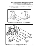
Figure 7.4 HEADLIGHT SECTION A
12
Summary of Contents for 10106
Page 29: ...Figure 8 8 Ford Ignition Diagram Duraspark II Systems Figure 8 11 Ford Switch Connectors 24...
Page 40: ...Diagram 1 Engine Wiring Diagram 35...
Page 41: ...Diagram 2 Instrument Panel Section Wiring Diagram 35...
Page 42: ...Diagram 3 Integrated Brake Lights Separate Turn Brake Lights 36...
Page 44: ......


