6.4
Terminal Installation and Making Connections
Note: In the following steps you will be making the circuit connections.
Before you start, you should carefully read Sections 7.0 through 11.0,
as appropriate, and continually refer to Section 12.0, DOUBLE-
CHECKING your routing and length calculations before cutting any
wires and making connections. GIVE SPECIAL ATTENTION TO TURN
SIGNAL AND IGNITION SWITCH CONNECTIONS. THESE CAN BE
CONFUSING.
6.4.1
Have all needed tools and connectors handy.
6.4.2
Select the correct size terminal for the wire and stud application.
6.4.3
Determine the correct wire length and cut the wire. Remember to allow enough
slack in the harness and wires at places where movement could possibly occur,
such as Jeep body to frame, frame to engine, etc. Double-check your
calculations.
6.4.4
Strip insulation away from wire. Strip only enough necessary for the type of
terminal lug you are using.
Note: In the following step, make sure that the terminal is crimped
with the proper die in the crimping tool. An improper crimp will
NOT make a good connection.
6.4.5
Crimp the terminal onto the wire. CAUTION: DO NOT OVER-CRIMP!
6.4.6
Connecting the harness throughout the groups is a redundant process. Make
sure that each wire is FIRST properly routed and THEN attach. DO NOT ATTACH
FIRST THEN ROUTE AFTERWARDS.
6.4.7 When all wires are attached, tighten the mounts and ties to secure harness
permanently.
6.5
MIDI FUSE
6.5.1
A large, inline MIDI fuse is included in the “ALTERNATOR” bag kit. This inline
fuse provides a fused link between the alternator and battery.
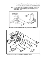
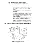
Figure 6.1 MIDI-Fuse
6.5.2
Find a suitable location close to the battery or starter solenoid. A drill with a ¼”
nut driver is required in order to install the (2) self-tapping screws provided.
7
Summary of Contents for 10106
Page 29: ...Figure 8 8 Ford Ignition Diagram Duraspark II Systems Figure 8 11 Ford Switch Connectors 24...
Page 40: ...Diagram 1 Engine Wiring Diagram 35...
Page 41: ...Diagram 2 Instrument Panel Section Wiring Diagram 35...
Page 42: ...Diagram 3 Integrated Brake Lights Separate Turn Brake Lights 36...
Page 44: ......


