8.2
1975 to 1978
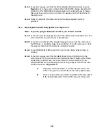
Note: 1975-1978 could have either Motorcraft or Delco systems installed.
8.2.1
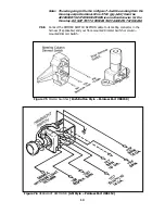
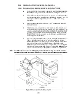
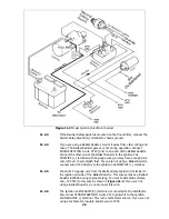
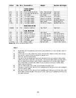
Motorcraft Alternator (2 configurations). See Figure 8.3.
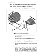
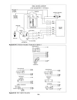
Note: Your Alternator may not appear exactly as represented in
Figure 8.5. The circuits are wired the same way, though.
Figure 8.3 Motorcraft Alternator (2 configurations)
A.
Connect the provided 6 gauge red wire to the Alternator Output lug
(Bat). Connect ENGINE SECTION wire #714 (wht) to the Voltage
Regulator (l) terminal.
B.
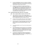
Connect wire #795 (red) to the Voltage Regulator A terminal.
C.
Connect a 14-gauge wire from the Voltage Regulator S terminal to the S
terminal of Alternator. Connect a 14-gauge wire from the Voltage
Regulator F terminal to the Alternator Field (F) terminal.
D.
Connect the Alternator Ground lug and the Voltage Regulator to chassis
ground.
E.
An alternate (and less-used) method is to omit the Alternator Stator (S)
wire, install a 14-gauge jumper across Voltage Regulator terminals A and
S, and connect wire #714 to either the A or S terminal on the Voltage
Regulator. The FIELD wire and the output wire from the alternator are
connected as above. The Voltage Regulator Ignition (l) terminal is not
connected and wire #795 (red) will not be used. Install ground wires as
in Section 8.2.1, Step D. This alternate configuration is illustrated in
dashed lines in Figure 8.5.
18
Summary of Contents for 10106
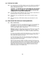
Page 29: ...Figure 8 8 Ford Ignition Diagram Duraspark II Systems Figure 8 11 Ford Switch Connectors 24...
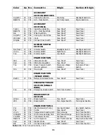
Page 40: ...Diagram 1 Engine Wiring Diagram 35...
Page 41: ...Diagram 2 Instrument Panel Section Wiring Diagram 35...
Page 42: ...Diagram 3 Integrated Brake Lights Separate Turn Brake Lights 36...
Page 44: ......


