8.0
CHARGING AND IGNITION SYSTEMS – AS ORIGINALLY
MANUFACTURED BY JEEP
CAUTION: IF YOU ARE USING A HIGH AMPERAGE (65 AMPS
OR HIGHER) ALTERNATOR SEE SPECIAL
INSTRUCTION SHEET PP-662 INCLUDED IN THIS
KIT. IF YOU DID NOT GET THIS, PLEASE CALL THE
TECH LINE AT 800-423-9696 OR SEND AN E-MAIL
TO
.
8.1
1974 and Earlier
8.1.1
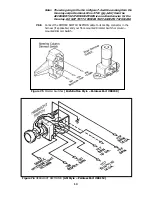
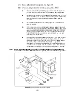
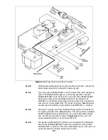
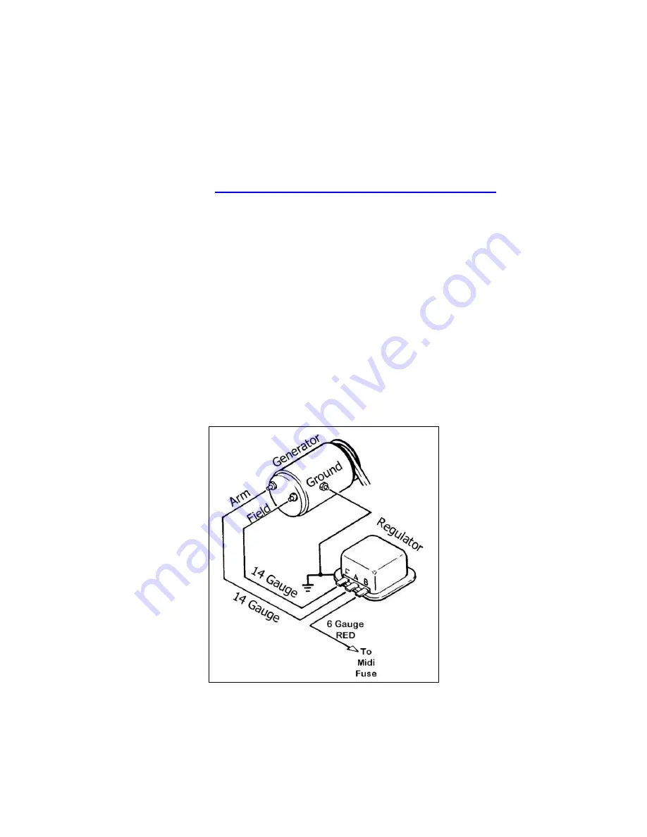
Generator Charging System. See Figure 8.1.
A.
Connect Generator ARMATURE terminal (A) to Voltage Regulator
terminal A. Connect Generator FIELD terminal (F) to Voltage Regulator
terminal F. Use 14-gauge wire (color optional).
B.
Be sure both the generator and the voltage regulator are securely
grounded. The voltage regulator may have a terminal for this purpose
(labeled “G”) or you may have to ground the regulator case.
C.
Connect the provided 6 gauge red wire to Voltage Regulator terminal B.
D.
Insulate and stow ENGINE SECTION wire #714 (wht).
Figure 8.1 Generator Charging System
16
Summary of Contents for 10106
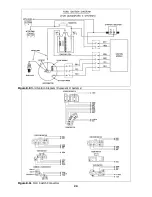
Page 29: ...Figure 8 8 Ford Ignition Diagram Duraspark II Systems Figure 8 11 Ford Switch Connectors 24...
Page 40: ...Diagram 1 Engine Wiring Diagram 35...
Page 41: ...Diagram 2 Instrument Panel Section Wiring Diagram 35...
Page 42: ...Diagram 3 Integrated Brake Lights Separate Turn Brake Lights 36...
Page 44: ......


