12.0
TESTING THE SYSTEM
12.1
Use a small (10 amp or less) battery charger to power up the vehicle for circuit testing. If
there is a problem anywhere, the battery charger’s low amperage and internal circuit
breaker will provide circuit protection.
CAUTION: IF YOU HAVE NOT YET DISCONNECTED THE BATTERY
FROM THE JEEP, DO SO NOW! DO NOT CONNECT THE BATTERY
CHARGER WITH THE BATTERY CONNECTED.
12.2
Connect the battery charger’s NEGATIVE output to the Jeep chassis or engine block and
its POSITIVE output to the Jeep’s positive battery terminal.
12.3
INDIVIDUALLY turn on each light, ignition, wiper circuit, etc. and check for proper
operation.
12.4
When all circuits check out THEN attach the battery cable to the battery for vehicle
operation.
13.0
WIRE CONNECTION INDEX AND FUSE REQUIREMENTS
13.1
Wire Connection Index
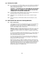
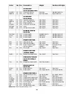
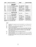
In each section, connect the wire, as identified by its wire color, to the appropriate item
in the CONNECT TO column. Pay close attention to the Notes in this section, as
identified by a small, raised number such as the one at the end of this sentence.
The
term “B+” means “Battery Positive” or Battery Power.
Table 12.1 is divided into sections that correspond to the sections of your wire harness,
(ACCESSORY SECTION B+, DIMMER SWITCH SECTION, etc.). The index is divided
vertically into six columns: COLOR, GA., NO., CONNECT TO, ORIGIN, and SECTION OF
ORIGIN.
The columns labeled ORIGIN and SECTION OF ORIGIN are for your reference ONLY. The
items in these columns tell you where each wire originates (ORIGIN) and from which
section (SECTION OF ORIGIN) of the harness.
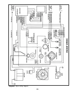
The column labeled NO. contains a 700 series number that is used to identify various
wires in the wiring diagrams that are a part of these instructions. These numbers are
physically marked on the wires themselves.
Many (but not all) of the wire numbers occur TWICE in this index. That is because you
will be connecting BOTH ENDS of many of the particular wire segments. However, some
wire segments are pre-connected at one end. For instance, all wires originating from the
fuse panel and certain other wires such as those originating from the horn relay, the
dimmer switch, and the instrument panel section. These pre-constructed wires are
identified by an asterisk (*) in the ORIGIN column.
30
Summary of Contents for 10106
Page 29: ...Figure 8 8 Ford Ignition Diagram Duraspark II Systems Figure 8 11 Ford Switch Connectors 24...
Page 40: ...Diagram 1 Engine Wiring Diagram 35...
Page 41: ...Diagram 2 Instrument Panel Section Wiring Diagram 35...
Page 42: ...Diagram 3 Integrated Brake Lights Separate Turn Brake Lights 36...
Page 44: ......


