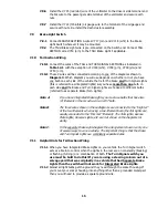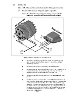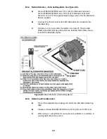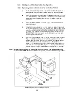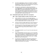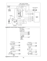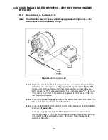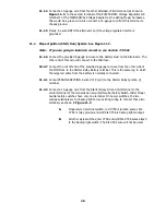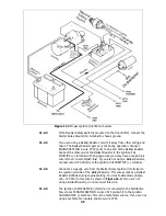
Figure 11.2 Mopar Ignition (Start/Run) System
11.2.3
If the Neutral Safety Switch is mounted on the floor shifter, connect the
Starter Relay Ground (G) terminal to chassis ground.
11.2.4
If you are using a Ballast Resistor, mount it away from other wiring and
hoses. The Ballast Resistor gets very hot during operation. Connect
ENGINE SECTION A wire #720 (pnk) to one end of the Ballast Resistor.
Connect the other end of the Ballast Resistor to the Ignition Coil
POSITIVE (+) terminal with 14-gauge wire (you may have enough pink
wire left over to accomplish this). If you are not using a Ballast Resistor,
connect wire #720 directly to the Ignition Coil POSITIVE (+) terminal.
11.2.5
Connect a 14-gauge wire from the Starter Relay Ignition (l) terminal to
the ignition coil side of the Ballast Resistor. This wire serves as a Ballast
Resistor BYPASS during engine starting. You must add a diode (8-amp
min., 100 PIV) to this wire as shown in Figure 11.2. If you are not
using a Ballast Resistor, do not connect this wire.
11.2.6
The Ignition Coil NEGATIVE (-) terminal is connected to the Distributor.
Also connect ENGINE SECTION A wire #723 (pur/wht) to the Ignition
Coil NEGATIVE (-) terminal. This is the tachometer source. If you are not
using a tachometer, insulate and stow wire #723.
29
Summary of Contents for 10106
Page 29: ...Figure 8 8 Ford Ignition Diagram Duraspark II Systems Figure 8 11 Ford Switch Connectors 24...
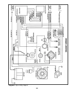
Page 40: ...Diagram 1 Engine Wiring Diagram 35...
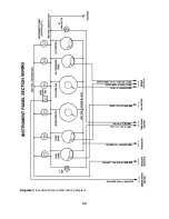
Page 41: ...Diagram 2 Instrument Panel Section Wiring Diagram 35...
Page 42: ...Diagram 3 Integrated Brake Lights Separate Turn Brake Lights 36...
Page 44: ......

