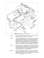
11.1.4
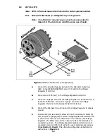
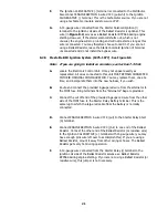
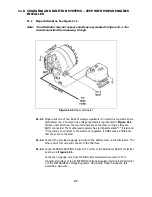
Connect a 14-gauge wire from the other Alternator Field terminal (as shown in
Figure 11-1) to the second terminal of the ELECTRONIC Voltage Regulator OR
terminal F of the MECHANICAL Voltage Regulator. On existing Mopar harnesses,
this would be a green wire. Also connect a 14-gauge wire from this terminal to
chassis ground.
11.1.5
Finally, be sure BOTH the alternator and the voltage regulator itself are
grounded.
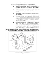
11.2 Mopar Ignition (Start/Run) System. See Figure 11.2.
Note: If you are going to install an ammeter, see Section 7.3 first.
11.1.6
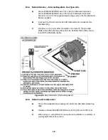
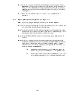
Connect the provided 6 gauge red wire to the battery stud on the Alternator. The
other end of this wire will connect to the Midi fuse.
10.2.7
Connect the cut off end of the provided 6 gauge red wire from the other side of
the MIDI fuse to the Starter Relay Battery terminal. This is the same lug to which
the large red cable from the battery is normally connected.
11.2.1
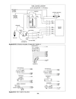
Connect ENGINE SECTION A wire #719 (pur) to the Starter Relay Ignition (l)
terminal.
11.2.2
Connect a 14-gauge wire from the Starter Relay Ground (G) terminal to the
center terminal of the transmission mounted Neutral Safety Switch. Older Mopar
neutral safety switches have only one terminal. On newer switches, the two
outside terminals are for backup lights. Use existing wiring to connect these two
terminals as shown in Figure 11.2.
A.
Mopar style 3 terminal switch; red #758 is ignition power, blk
#783 is relay ground and wht/blk #756 is backup lights output.
B.
All other style switches; red #758 and wht/blk #756 wires attach
to the backup light switch. The blk #783 wire will not be used.
28
Summary of Contents for 10106
Page 29: ...Figure 8 8 Ford Ignition Diagram Duraspark II Systems Figure 8 11 Ford Switch Connectors 24...
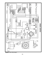
Page 40: ...Diagram 1 Engine Wiring Diagram 35...
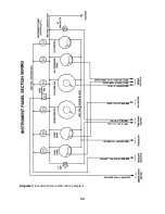
Page 41: ...Diagram 2 Instrument Panel Section Wiring Diagram 35...
Page 42: ...Diagram 3 Integrated Brake Lights Separate Turn Brake Lights 36...
Page 44: ......


