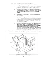
Note: The wire going to the fan in Figure 7.4 will be coming from the
fan relay output terminal. Wire #701 (gry/wht) from the
ACCESSORY SECTION SWITCHES is an activation wire for the
fan relay. DO NOT TRY TO POWER THE FAN WITH THIS WIRE.
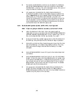
7.6.5 Connect the DIMMER SWITCH SECTION cable to its mating connector in the
harness (if applicable) and your floor-mounted Dimmer Switch or column-
mounted Dimmer Switch.
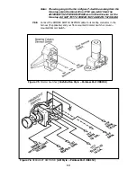
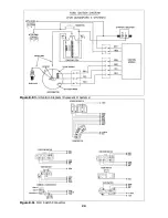
Figure 7.5 Dimmer Switches (Push Button Style – Painless Part #80150)
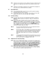
Figure 7.6 HEADLIGHT SECTION B (GM Style – Painless Part #80152)
13
Summary of Contents for 10106
Page 29: ...Figure 8 8 Ford Ignition Diagram Duraspark II Systems Figure 8 11 Ford Switch Connectors 24...
Page 40: ...Diagram 1 Engine Wiring Diagram 35...
Page 41: ...Diagram 2 Instrument Panel Section Wiring Diagram 35...
Page 42: ...Diagram 3 Integrated Brake Lights Separate Turn Brake Lights 36...
Page 44: ......


