


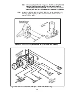


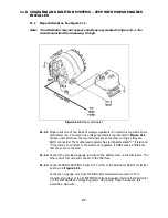

Figure 7.7 Painless Fan Relay Kit (Part #30101)
7.7
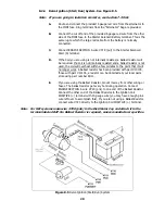
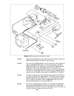
HEADLIGHT SECTION B Wiring. See Figure 7-6.
7.7.1 Connect the 6 wires of HEADLIGHT SECTION B, the Dome and Interior Light
return circuit, and the Headlamp Switch Ground as shown. If you do not have a
GM headlight switch, you should trace out the wires of your existing harness and
connect the new harness according to Table 12-1.
Note: On late-style GM headlight switches, the park lights terminal to which
wire #727 (brn) is connected (shown in Figure 7-6) has been omitted.
In this case, wire #727 must be connected as indicated by the dashed
line in Figure 7-6.
7.8
Instrument Panel
7.8.1
Connect the wires of the INSTRUMENT PANEL SECTION as indicated in Table
12-1. Insulate and stow any wires you do not use.
7.8.2
Connect a jumper from wire #735 (red/wht) to all Gauges' power or “I”
terminals. Connect a jumper from wire #730 (brn) to all Gauges' Instrument
Lighting terminals. Connect a jumper to all Gauges' Ground terminals and
connect to Chassis Ground.
7.8.3
Install the #721 (Lt.Grn) temperature gauge sender wire on the single long post
on back of the temperature gauge.
Note: These terminals were originally a push on terminal and now are an
eyelet terminal. Nuts to attach each terminal are provided in the parts
kit.
7.8.4
Install the #739 pnk wire on the fuel gauge post closest to the glove box and
secure with a nut.
7.8.5
Attach the blk wire to a good ground such as a cluster mounting screw.
14
Summary of Contents for 10106
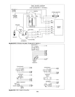
Page 29: ...Figure 8 8 Ford Ignition Diagram Duraspark II Systems Figure 8 11 Ford Switch Connectors 24...
Page 40: ...Diagram 1 Engine Wiring Diagram 35...
Page 41: ...Diagram 2 Instrument Panel Section Wiring Diagram 35...
Page 42: ...Diagram 3 Integrated Brake Lights Separate Turn Brake Lights 36...
Page 44: ......