Operator's Manual
Issue 14
/
Mar 2016 / UMC0071
Mercury
iPS
©2016 Oxford Instruments NanoScience. All rights reserved.
Page
58
the group and they also enter quench mode. These units may have already quenched as their
terminal voltages will also have been high for a time close to the transient time.
In quench mode the PWM of each magnet device trips to zero so that the output of each device
is 0A. Once the terminal current has decayed below 1A a 20 second delay is initiated after
which the device outputs are clamped and the “Clamped” indicator on the Home screen will also
be asserted in red.
To clear the Quench mode, unclamp and reset the power supply group, tap “Hold”.
5.5 Vector Rotate mode
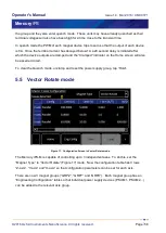
Figure 17. Configuration Screen in Vector Rotate mode.
The Mercury iPS-M is capable of controlling up to 3 independent axes. To do this, set the
“Magnet Type” to “Vector Rotate” (Figure 17) mode. Now the configuration table has 3 rows
“Z-axis”, “Y-axis” and “X-axis” so that configuration parameters can be set for each axis.
There are now 3 magnet groups (“GRPZ”, “GRPY” and “GRPX”). Each magnet group has an
“Engineering Configuration” table so that individual power supply devices (PSU.M1, PSU.M2...)
can be added to the relevant axis group.


