Operator's Manual
Issue 14
/
Mar 2016 / UMC0071
Mercury
iPS
©2016 Oxford Instruments NanoScience. All rights reserved.
Page
43
its position on the RS485 modbus. So for example, an iPS 240-10 is will consist of 1 x iPS-M
plus 3 x iPS-S units. The slaves detected should equal 3, the units will be labelled PSU.M1,
PSU.M2, PSU.M3 and PSU.M4. The slaves detected parameter (Figure 9) is updated every
time the iPS system is booted.
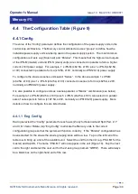
Figure 9. Magnet configuration screen of the Mercury iPS
4.3 Magnet Type
The “Magnet Type” drop down box allows the choice of three magnet types “Solenoid”, “Split
Pair” and Vector Rotate” (Figure 9). At the time of writing there is no operational difference
between Solenoid and Split Pair, these are just single axis current supply systems. A “Vector
Rotate” magnet however, is a set of 2 or 3 coil split-pairs arrange orthogonally to form a Z-axis
and an X-axis (2 coil pairs), or a Z-axis, X-axis and a Y-axis (3 coil pairs). Putting the Mercury
iPS into “Vector Rotate” mode will add Y-axis and X-axis rows to the “Config” table, will add Y-
axis and X-axis groups to the “Eng Config” pages and will add X-axis and Y-axis control panels
to the iPS Home screen.


