


Operator's Manual
Issue 14
/
Mar 2016 / UMC0071
Mercury
iPS
©2016 Oxford Instruments NanoScience. All rights reserved.
Page
79
9 Replace the top cover on to the iPS, reversing the procedure for removal.
7.2.3 Basic check of board operation
1 Power up the
Mercury
iPS. If fitted correctly, the iPS will detect the board and may request
permission to use it.
2 Put the iPS in Local mode by tapping the local/remote toggle button on the iPS
Home
page.
3 Tap
Settings,
scroll to and tap the
Devices
tab.
4 Scroll down the list of devices and find the level meter board. Also, scroll to the right to read
the firmware version.
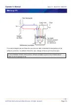
7.3 Connecting the level probe
Connect the level probe to the appropriate 9-way D-connector on the rear page of the board
using the cable supplied. For reference, the pin connections are as follows.
Pin
Signal Name
Helium Probe
Nitrogen Probe
1
VHIGH
V sense (Top)
n/c
2
VLOW
V sense (Bottom)
n/c
3
(Unused)
4
FREQ IN
Link to 5
OUTPUT FREQ (0 to 12 V)
5
FREQ OUT
Link to 4
n/c
6
I HIGH
I (Top)
n/c
7
I LOW
I (Bottom)
0 V
8
+12 V
n/c
+12V (20 mA maximum
9
CHASSIS GND
Screen
Screen
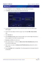
7.4 Configuring Mercury
iPS
for helium level meter
1 Tap an unconfigured widget on the
Home
page to display the
Channel Display
Configuration
page.
2 Tap the
Device
box and select a level meter device from the drop down list (an example is
shown).


