Operator's Manual
Issue 14
/
Mar 2016 / UMC0071
Mercury
iPS
©2016 Oxford Instruments NanoScience. All rights reserved.
Page
60
6 TEMPERATURE MEASUREMENT
Standard
Mercury
iPS’s are fitted with one temperature board. The temperature board will
typically be used to measure the magnet temperature but may also be used to measure the
switch temperature.
The iPS can accept the following sensor types:
Negative temperature coefficient (NTC) resistance
Positive temperature coefficient (PTC) resistance
Thermocouple
Silicon diode
Each input can be read at a maximum rate of 4Hz. The iPS can detect short-circuit inputs and
open-circuit inputs. The iPS contains a temperature sensor that is used to compensate for
fluctuations in ambient temperature.
This chapter covers the following topics.
Cabling requirements
Configuring the temperature sensor
Using a generic calibration file (if applicable) + generic sensor adjustment
More about thermocouples
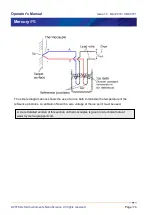
See chapter 11 for a description of the temperature sensor circuit.
6.1 Sensor connections
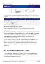
The temperature sensor input is connected via the 9-way D-connector on the rear panel of the
iPS marked “Sensor”.
Pin number
Connection
Male plug (cable)
1
Sensor input high
2
Sensor input screen.
3
Sensor input low
4
Current ve
5
Current source -ve


