Operator's Manual
Issue 14
/
Mar 2016 / UMC0071
Mercury
iPS
©2016 Oxford Instruments NanoScience. All rights reserved.
Page
138
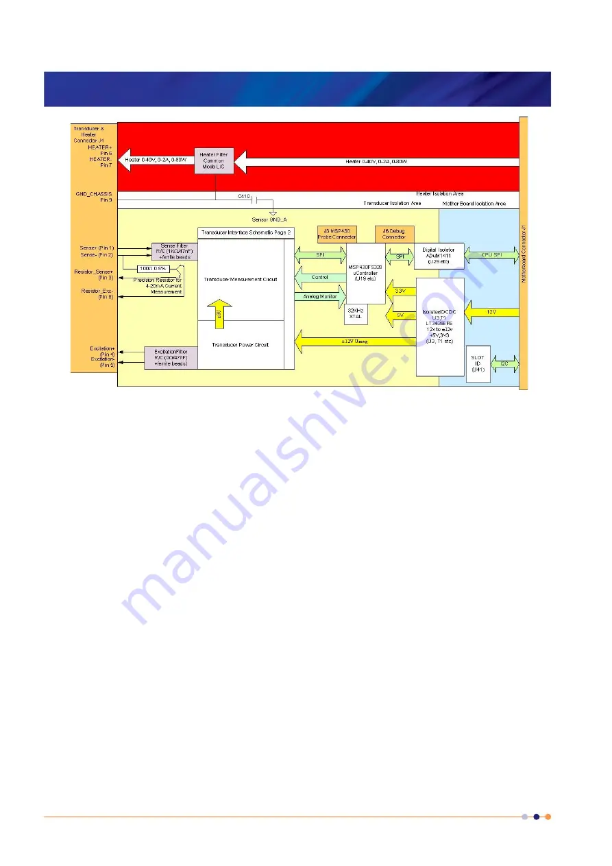
The circuit is powered from the CPU board 12 Volt supply. This enables the board to be used in
both
Mercury
iPS and iPS systems. The transducer interface is individually isolated on this
board. An isolated, low noise DC-DC converter is implemented by a LT3439EFE power supply
and transformer. The rectified and smoothed output provides ±12V unregulated supplies to
power the transducer interface, from which the +3.3V logic and +5V analog supplies are derived
using low noise fixed linear regulators.
The board is an SPI bus slave to the CPU board. A digital isolator chip (U29) drives Clock,
SIMO (Slave in Master out) Data and Chip select to the on board MSP430 from the CPU board.
SOMI Data is driven back to the CPU from the MSP430.
A slot identifier Chip U41 can be read by the CPU to give PCB type and version via the I
2
C bus.
The microcontroller is a 25MHz 16 bit mixed signal microcontroller from TI. It has 128Kbytes of
flash memory and 10Kbytes of SRAM. In addition to the SPI bus to the CPU board, a local SPI
bus interfaces to the external 24 bit ADC used to make pressure readings during operation. An
internal 12 bit ADC, using the same precision reference as the external ADC, is used t
o
monitor
the transducer excitation during operation. An external crystal ensures accurate timing. A bank
of 5 diagnostic LEDs is fitted at the top of the board. Connector J3 is an I/O port to initially
program the microcontroller in production. An additional serial/general purpose debug port is
provided on J6, although this is not currently used for user applications.


