background image


Operator's Manual 

Issue 14 

/

 Mar 2016 / UMC0071

Mercury

iPS


 ©2016 Oxford Instruments NanoScience. All rights reserved. 

Page 

108 

*CLS Clear Status Command 

*ESE Standard Event Status Enable Command 

*ESE? Standard Event Status Enable Query 

*ESR? Standard Event Status Register Query 

*OPC Operation Complete Command 

*OPC? Operation Complete Query 

*RST Reset Command 

*SRE Service Request Enable Command 

*SRE? Service Request Enable Query 

*STB? Read Status Byte Query 

*TST? Self-Test Query 

*WAI Wait-to-Continue Command 


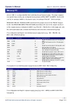
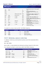
The identification command IS supported... 

*IDN? Identification Query 


10.3.1  SCPI protocols 

The commands are case-sensitive. 

Keywords are a maximum of four characters long. Keywords longer than four characters 
generate an invalid command response. 

Keywords are separated by a colon: (ASCII 0x3Ah). 

The maximum line length is 1024 bytes (characters), including line terminators. 

All command lines are terminated by the new line character 

\n

 (ASCII 0x0Ah). 

10.3.2  Reading the instrument identity 

Send the command: 

*IDN? (plus termination \n) 

Summary of Contents for NanoScience MercuryiPS

Page 1: ...NanoScience Issue 14 Mar 2016 Original Instructions MercuryiPS Power Supply for Superconducting Magnets Issue 14 Mar NanoScience All rights reserved Oxford Instruments NanoScience Original Instructio...

Page 2: ...AFETY 10 1 1 Warnings 10 1 1 1 Protective and functional ground 10 1 1 2 High voltage hazard 11 1 1 3 Maintenance and adjustment 11 1 1 4 Restrictions on use 11 1 2 Cautions 12 1 2 1 Electrostatic cau...

Page 3: ...yiPS for the first time 27 3 5 The MercuryiPS touch screen 27 3 5 1 The magnet home page 28 3 5 2 Custom home pages 30 3 5 3 Channel summary widget 30 3 5 4 Drop down menus 30 3 5 5 Scrolling 31 3 5 6...

Page 4: ...14 Htr Res 51 4 4 15 Sw Res 51 4 4 16 Lead 51 4 4 17 SW on ms 52 4 4 18 SW off ms 52 4 4 19 Catch 52 4 4 20 Epsilon A 52 5 OPERATING THE MAGNET 53 5 1 Rate Limits 54 5 2 Fast Rates Slow Rates 57 5 3...

Page 5: ...rmocouples 71 6 6 1 Thermocouple principles 71 6 6 2 Configuring for thermocouples 71 6 6 3 Reference junction compensation 73 6 6 4 External reference junctions 73 7 CRYOGEN LEVEL METER 75 7 1 Princi...

Page 6: ...0 9 2 Remote operation using GPIB 101 9 2 1 Configuring GPIB 101 9 2 2 GPIB Cabling requirements 102 9 3 Remote operation using Ethernet 102 9 3 1 Configuring Ethernet 102 9 3 2 Ethernet cabling requi...

Page 7: ...d 125 11 2 2 Basic check of board operation 126 11 3 Circuit description of the temperature sensor board 126 11 3 1 Voltage measurement mode 126 11 3 2 Resistance measurement in constant current mode...

Page 8: ...5 14 1 Description of the GPIB daughter board 145 14 2 Installing a GPIB board 145 14 2 1 Fitting the board 145 14 2 2 Basic check of board operation 145 14 3 Connecting to the GPIB board 146 15 PREVE...

Page 9: ...NanoScience All rights reserved 17 2 Electrical power supply 156 17 3 Magnet outputs 156 17 4 Sensor inputs 157 17 5 PC interfaces 158 17 6 Electrical isolation 158 17 7 Environmental specifications...

Page 10: ...training courses that are available Training requirements vary from country to country Users must ensure that training is given in accordance with all applicable local laws and regulations If any user...

Page 11: ...h ways that do not conflict with said applicable laws and regulations If the equipment is not installed used maintained refurbished modified and upgraded as specified by the manufacturer then the prot...

Page 12: ...s Handbook describing version 2 0 of MercuryiPS software 04 All pages Minor edits Generic Calibration GPIB customer support addresses to update to 2 2 x of MercuryiPS software 05 All pages Additional...

Page 13: ...arest support facility given on the last page of this manual and have the following details available Product name MercuryiPS Serial number A 9 character alphanumeric code starting with MM or MS locat...

Page 14: ...h the iPS all personnel must read and become thoroughly familiar with the information given in chapter 1 In particular users must read understand and strictly observe all Warning notices Caution notic...

Page 15: ...or damages howsoever caused This manual is provided without warranty of any kind either implied or expressed including but not limited to the implied warranties of merchantability and fitness for a p...

Page 16: ...ammable Read Only Memory ESSD ElectroStatic Sensitive Devices EOS End of String FET Field Effect Transistor FPGA Field Programmable Gate Array GPIB General Purpose Interface Bus IEEE 488 GUI Graphical...

Page 17: ...laboratory use Intertek Report No 101311638LHD 001 EN61326 1 2013 EMC Immunity standard EN55011 2009 A1 2010 Emissions standard Electrical equipment for measurement control and laboratory use EMC req...

Page 18: ...ield applications in physical science research and process development down to the atomic scale The business has a strong capability in advanced cryogenics and applied superconductivity Through the ap...

Page 19: ...ou must take to ensure your own safety 1 1 1Protective and functional ground The equipment must be connected to an electrical ground The ground wire green yellow in the equipment power cable must be c...

Page 20: ...must remain accessible for disconnection of the equipment 1 1 3Maintenance and adjustment Only qualified and authorised persons must service or repair this equipment Under no circumstances must the us...

Page 21: ...ues ESD Utiliser des proc dures ESD homologu es lors de l installation ou de la maintenance de ce produit 1 2 2Cooling caution Internal components in this equipment are air cooled Ensure that the side...

Page 22: ...taneously operated in a confined space then background noise may become excessive UNIT MULTIPLE DE BRUIT Si de nombreux MercuryiPS unit s doivent fonctionner simultan ment dans un espace confin puis l...

Page 23: ...The first digit of this number indicates the major version of the firmware and the second two digits indicate minor revisions The basic unit includes a bipolar magnet output Additional slave units can...

Page 24: ...mode power supply inside the iPS M The On Off button illuminates blue when the iPS is powered up The iPS S Slave has a blue indicator LED to show when it is powered up Any Slave connected to a Master...

Page 25: ...s are labelled 2 2 Electrical power supply The MercuryiPS automatically configures itself to match the supplied electrical power as long as the voltage and frequency are within the specified ranges No...

Page 26: ...t amplifies scales and filters the voltage produced by the sensor This conditioned voltage is then passed to a 24 bit analogue to digital converter ADC Some sensors e g resistance sensors require exci...

Page 27: ...nterfaces are located on the rear panel of the iPS Oxford Instruments NanoScience ISOBUS ISOBUS allows a single RS232 port on a computer to control a number of instruments independently This arrangeme...

Page 28: ...2 6 Main components This section gives a brief description of the internal components of the MercuryiPS Figure 3 shows how these components are arranged inside the MercuryiPS enclosure Figure 3 View...

Page 29: ...extracts the heated air from the rear of the unit A third high power fan is used to cool the large finned aluminium heat sink of the run down power resistors This fan only cuts in when required usual...

Page 30: ...r 1 is adjacent to the power supply in the iPS The iPS can therefore accept up to 8 daughter boards These can consist of combinations of the following board types Temperature sensor This is a board co...

Page 31: ...em A maximum of eight of these boards can be fitted Chapter 13 gives a full technical description The iPS automatically identifies every daughter board present Figure 4 Layout of MercuryiPS expansion...

Page 32: ...al is inverted and passed to an error amplifier where it is summed with the buffered output voltage from a precision high power low temperature coefficient sense resistor which is measuring the main o...

Page 33: ...raise the temperature significantly the powerful fan will cut in to prevent the run down resistors from over heating It would be normal to hear the run down fan cutting in during magnet rundown altho...

Page 34: ...e MercuryiPS automatically configures itself to match the supplied electrical power supply If the voltage and frequency are within the specified ranges see section 17 2 no user intervention is require...

Page 35: ...y cable included with the equipment UTILISEZ UNIQUEMENT LE C BLE FOURNI Utilisez uniquement le c ble d alimentation lectrique fourni avec l quipement Connect the equipment to an electrical supply usin...

Page 36: ...1 Operate the switch on the rear panel of the Mercury so that the 1 is depressed 2 Press the Power button on the left of the front panel The button illuminates blue 3 The MercuryiPS initialises then t...

Page 37: ...of the Home page shows examples of buttons To initiate an action tap the button once The button will change colour when active either flashing ORANGE or switching between ORANGE and a dark background...

Page 38: ...and field Tesla modes Interface connect disconnect button The button displays one of the following letters E if the ethernet interface is selected I if the Isobus interface is selected U if the USB in...

Page 39: ...the widget has not been configured it displays the name None and the value 0 0000 If the widget has been configured it displays the following information Channel identifier or nickname The main displa...

Page 40: ...the item 3 5 5 Scrolling On some pages there is not enough space to display all the keys or information associated with the page This is indicated by a button with the label or Tap the button to scrol...

Page 41: ...once to delete the last character entered To delete or edit a single digit within the number touch the digit to highlight it then tap Del or tap the new digit To delete or edit several digits within t...

Page 42: ...the new character To delete or edit several characters within the string touch the characters until they are highlighted then tap Del or tap the new characters Tap OK to save the text that has been en...

Page 43: ...o enter a new value using the numeric keypad Tap once to increase the displayed value 3 5 8 Button labels The label on some buttons changes depending on the button function The label on most buttons d...

Page 44: ...Tap once to save changes in a table Tap or once to save changes to the page Tap or to leave the current page without making any changes 3 5 10 Setting the date and time This process is a simple exampl...

Page 45: ...iPS touch screen The MercuryiPS touch screen allows the user to monitor up to 6 signals as a function of time 3 6 1 Plot Configuration The Plot Configuration page is used to set up which signals are t...

Page 46: ...her view signals from all boards fitted as shown above or view the signals from a single board as shown below for MB0 H1 Scroll and tap to select a signal Then use the button to move the signal to the...

Page 47: ...Place a finger on the region of interest of the plot The re scaled plot will be centred around this position 2 Drag the finger to zoom in and out around the area of interest a Drag the finger to the r...

Page 48: ...Operator s Manual Issue 14 Mar 2016 UMC0071 MercuryiPS 2016 Oxford Instruments NanoScience All rights reserved Page 39...

Page 49: ...olenoid magnet fitted with a persistence switch In this example the persistence switch heater is ON the switch is open and the current from the psu flows through the magnet When the switch heater is O...

Page 50: ...because they over heat if they are ramped too fast Figure 8 Diagram showing a simple solenoid magnet fitted with a persistence switch In this example the persistence switch heater is OFF the switch is...

Page 51: ...l by switching in the rundown resistors to dump excess current but if the magnet has actually quenched the terminal voltage will continue to rise For some magnets there is a possibility that a small w...

Page 52: ...agnet Type The Magnet Type drop down box allows the choice of three magnet types Solenoid Split Pair and Vector Rotate Figure 9 At the time of writing there is no operational difference between Soleno...

Page 53: ...0V connected in series to form a 62 5A 20V nominally an iPS60 20 power supply It is also possible to configure units as a series parallel or Matrix combination see below For example 1 x iPS M 62 5A 10...

Page 54: ...the bottom corners of the Engineering Configuration page If the Series configuration has been selected for the Z axis the Z axis grouping table will be a column Tap on the top cell of the column and p...

Page 55: ...U M1 and PSU M2 in a 60A 20V series pair in parallel with PSU M3 and PSU M4 as a 60A 20V series pair and theses in parallel with PSU M5 and PSU M6 as a 60A 20V series pair The 3 pairs in parallel give...

Page 56: ...mple if the Z axis group GRPZ is configured as a 180 10 3 units in parallel and if the limit current was set to 169 00A this would be a total limit of 169A which would be 169 3 56 3333A limit for each...

Page 57: ...Transient Time is used in conjunction with the Voltage Limit see above as a mechanism of magnet QUENCH detection If the measured voltage at the group output terminals exceeds the voltage limit for lo...

Page 58: ...re is used as a safety threshold for safe running of the magnet The threshold value for safe operation is defined by the Limit K value see below If the magnet temperature signal is coming in via the i...

Page 59: ...at a safe slow rate If the magnet is persistent the iPS group will ramp up to the last known magnet current turn on the switch heater to pick up the magnet ramp the magnet to zero then turn off the sw...

Page 60: ...er current is calculated as R R R I V I I SwHtr Switch leads op op SwHtr SwHtr 2 2 0 Therefore the iPS system adjusts the switch heater current based on the variation of the voltage across the switch...

Page 61: ...es breaks open the iPS group detects this and rapidly ramps the current up to match the magnet current It will then turn on the switch heater to HOLD the magnet current at the caught value Then a curr...

Page 62: ...A display of the Home page Note if the Home page is in Tesla mode tap on the Field T display This will bring up the Set Point Set Rate page show below Figure 14 To enter a set point tap on the Set Poi...

Page 63: ...which would be a parallel group of 1 x iPS M plus 2 x iPS S s and if a set point of 150A were entered the target currents would be distributed as 50A for each of the 3 parallel units iPS M iPS S1 and...

Page 64: ...ecifies the type of rate limit that is being defined Column 2 From A specifies the lower current at which the limit will be applied Column 3 To A specifies the upper current at which the limit will be...

Page 65: ...all the time for systems configured without a persistent switch because for systems without a switch ramping the output will always be ramping the magnet The rates are applied as a coercive limit If...

Page 66: ...he table tap the row number on the left hand side then tap the button in the bottom left corner A dialogue box will show a message indicating which row you are about to remove Tap OK to remove it 5 4...

Page 67: ...uts are clamped and the Clamped indicator on the Home screen will also be asserted in red To clear the Quench mode unclamp and reset the power supply group tap Hold 5 5 Vector Rotate mode Figure 17 Co...

Page 68: ...wer supply devices configured in the axis groups of GRPX or GRPY The panels whilst cut down still have the essential controls which function in the same way as the standard solenoid Home screen To see...

Page 69: ...at a maximum rate of 4Hz The iPS can detect short circuit inputs and open circuit inputs The iPS contains a temperature sensor that is used to compensate for fluctuations in ambient temperature This...

Page 70: ...s achieved by connecting together pins 3 4 and 5 of the 9 way D connector see table above Biasing the thermocouple in this way prevents error currents flowing in the thermocouple even if the equipoten...

Page 71: ...and choose a temperature sensor input from the drop down list This will be labelled T1 DB6 T1 in the example below Then tap OK 3 Tap Signal and select Temperature Then tap OK 4 Finally tap Assign to s...

Page 72: ...mV 2 Tap the Sensor Type parameter box and select a sensor type from the drop down menu Sensor types include a thermocouple b PTC positive temperature coefficient sensor c NTC negative temperature coe...

Page 73: ...red tap the parameter box containing the name of the sensor and enter a new name e g Change DB3 T1 to Example 8 Cal Adj Tap once to access the Generic Sensor Adjustment page see section 6 4 2 This all...

Page 74: ...ally near the high resistance end of the range If a scale adjustment of more than a few percent is required to correct the temperature reading investigate the measurement set up to check there is not...

Page 75: ...ibration and from the drop down list select the generic file corresponding to the sensor This example selects RP51 dat for a PT100 3 Tap Cal Adj to open the Generic Sensor Adjustment page 4 Place the...

Page 76: ...es This acts as a voltage source based on the Seebeck effect the output voltage of which increases with increasing temperature difference The iPS contains cold junction compensation so a reference jun...

Page 77: ...possible at low temperatures 6 5 5Excitation current Resistance and diode sensors require an excitation current A 4 wire connection is used for these sensors When the circuit is configured to measure...

Page 78: ...ration files with dat or prn extensions A calibration file contains a number of discrete data pairs each mapping a sensor reading on to a temperature value The first column is the output eg temperatur...

Page 79: ...Allen Bradley 4 to 250K CS 01 470R Speer 0 25 to 9 999K Your MercuryiPS may not have all the above calibration files pre loaded 1 The Lin and Null ranges are general purpose ranges that may be config...

Page 80: ...e conductor gives rise to a thermoelectric emf T which is a function of the temperature gradient T The precise form of T is determined by scattering of the conduction electrons by the lattice which is...

Page 81: ...tion 6 2 set the sensor type to Thermocouple In the example page below the reference is External since a liquid nitrogen reference is used rather than the ADT7310 Under Sensor readings the upper T K i...

Page 82: ...pins 1 and 3 of the D connector which can be 0 5C or more an assumption that the internal reference chip is 2 0C warmer than pins 1 and 3 in the 9 way D connector This figure derived from tests is als...

Page 83: ...erved Page 74 The simple diagram above shows the use of an ice bath to maintain the temperature of the reference junctions A calibration file with a zero voltage at the ice point must be used A more d...

Page 84: ...n the gas above the liquid The level meter controls the current through the wire such that the temperature of the section in the gas is above the critical temperature and is thus resistive while the s...

Page 85: ...er the liquid surface increases by approximately 45 The probe head includes an oscillator whose frequency depends on the capacitance of the probe Thus the oscillator frequency also depends on the leve...

Page 86: ...screws that secure the top clamping bracket Figure 19 Remove the board clamp Figure 19 MercuryiPS daughter board clamp 3 Knock out the blanking plate Figure 20 in the location where the board is to be...

Page 87: ...nsert the retaining screw to hold the card Do not tighten at this time 7 From the top of the iPS replace the top retaining bracket and replace its screws Make any small adjustments to the card positio...

Page 88: ...croll to the right to read the firmware version 7 3 Connecting the level probe Connect the level probe to the appropriate 9 way D connector on the rear page of the board using the cable supplied For r...

Page 89: ...r widget on the Home page to open the Level Meter Sensor Details page 7 Tap the Helium tab 8 Set the Resistance at 0 equal to 178 active length m The active length of the probe in mm is engraved on th...

Page 90: ...n page 15 Tap Signal and select Helium Level 16 Tap Assign to save the changes and return to the Home page The level meter widget now reads the helium level 7 5 Configuring MercuryiPS for nitrogen lev...

Page 91: ...et on the Home page to open the Level Meter Sensor Details page 8 Tap the Nitrogen tab 9 Set the Pulse Counting Period ms to 750 10 Connect the nitrogen level probe to the level meter board at the rea...

Page 92: ...page 13 Tap the level meter widget twice to return to the Channel Display Configuration page 14 Tap Signal and select N2 Level 15 Tap Assign to save the changes and return to the Home page Increasing...

Page 93: ...e page and using the scroll button GUI pages for remote operation RS232 GPIB Ethernet are described in chapter 9 below 8 1 General View the General settings page by selecting the General tab The page...

Page 94: ...truments The Application version number The number in the lower left corner of the screen is the Cryosys Application version number Cryosys is the main application running on any Mercury unit providin...

Page 95: ...vels The temperature controller can be configured to vary the display brightness to match the ambient light level auto dim feature Toggle On Off to turn on off the auto dim feature Timeout sec Set the...

Page 96: ...d blue style black refers to the style with a plain black background as shown in the example below The Display page also contains the following buttons Alarm Tap once to access the Alarm Logs page see...

Page 97: ...e lists which boards are fitted in which slot The columns show Row number The number of the slot ID The ID identity of the board fitted in this slot MB for mother board DB for daughter board and a num...

Page 98: ...1 1 If the text is RED an alarm condition exists Home Tap once to return to the Home page Tap once in any row to switch to the appropriate configuration page for the device 8 4 Clock Select the Clock...

Page 99: ...to return to the Home page 8 5 File transfer Select File Transfer to view a page used to load calibration files into the controller from a USB memory stick The memory stick is fitted into the USB A so...

Page 100: ...the MercuryiPS and allows the user to interact with the instrument using the touch screen GUI It translates and communicates user commands to the appropriate device board The device board firmware is...

Page 101: ...st of available update files Select APPLICATION from the list 7 Tap File and select the firmware file which is cryosys_update tar 8 Tap Apply Confirm that you wish to update by tapping the OK button o...

Page 102: ...hanges to revert to the old firmware version 12 Power the system down and wait 30 seconds before applying power again 8 7 Access Level This page allows the user to enter ENGINEERING mode to access fea...

Page 103: ...Password box The alphanumeric window opens Enter the password 5 Tap Apply With the correct password the message Password Correct Engineering mode now enabled appears 6 Tap Change Password to change t...

Page 104: ...ve the configuration of the MercuryiPS The user can then restore a previously saved configuration The page contains the following parameter boxes and controls Save configuration To save the present sy...

Page 105: ...ages All function in the same way so only one is described in this section This page below appears when editing a PID file This page contains the following parameter boxes and controls Main area Displ...

Page 106: ...w appears when editing a PID file This page contains the following parameter boxes and controls Main area Displays a list of the existing files of this type Tap a filename to select it The name of the...

Page 107: ...XION Lors de la connexion un PC le syst me peut se connecter un PC qui est conforme une ancienne version de la norme 60950 1 o le niveau de conditionnement d humidit sp cifique est inf rieure Dans cet...

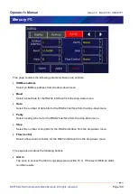
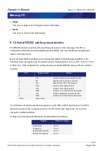
Page 108: ...drop down menu Data Select the number of data bits for the RS232 interface from the drop down menu Parity Select a parity scheme for the RS232 interface from the drop down menu Stop Select the number...

Page 109: ...c If the computer has a 9 way D plug a standard RS232 9 way to 25 way cable is required Pin Signal name Notes 1 FG Linked to chassis ground inside the iPS 2 TD Data from the computer to the iPS 3 RD D...

Page 110: ...tains one parameter box GPIB Address Select a GPIB address for this instrument from the drop down menu NOTE This sets the GPIB Primary Address When using the SCPI command set the GPIB Secondary Addres...

Page 111: ...ments are powered up Equipment damage can result if this precaution is not observed D BRANCHEMENT DU CORDON Ne pas brancher ou d brancher des cordons de bus d interface g n ral pendant que l ordinateu...

Page 112: ...he network If DHCP is set to Off the values entered in the IP Address Subnet and Gateway parameter boxes are used IP Address If dynamic host configuration protocol DCHP is set to Off enter the IP addr...

Page 113: ...to one communication with a computer USB 2 0 full speed 12 MBits per second is supported The USB port is configured to emulate a serial port 9 4 1Configuring USB Since USB is a one to one connection n...

Page 114: ...the iPS A quicker way to switch off disable the remote interface is from the Home screen The virtual button in the bottom left corner see Figure 13 If the virtual button is orange red the remote inte...

Page 115: ...e date of this manual these include NI LV VIs This is a library of Vi s for National Instruments LabView version 8 6 and later Communication with MagLab over ISOBUS This document is a guideline on how...

Page 116: ...on the SCPI command set although the iPS may not be fully compliant with SCPI Legacy commands were used in previous power supply models e g IPS120 10 The user configures the iPS to use one set or the...

Page 117: ...able Query STB Read Status Byte Query TST Self Test Query WAI Wait to Continue Command The identification command IS supported IDN Identification Query 10 3 1 SCPI protocols The commands are case sens...

Page 118: ...y after the term that cannot be interpreted 10 3 4 Verbs The interface controller can only issue two verbs READ A query command reading information on the specified noun SET Updates information for th...

Page 119: ...tains a number of Signals The structure of NOUNS reflects this For instance DEV UID TYPE1 SIG TYPE2 encompasses examples for TYPE1 TEMP HTR LVL GAS examples for TYPE2 VOLT CURR POWR RES TEMP SLOP HEL...

Page 120: ...ser level SYS LOCK OFF SOFT ON W Sets the lock mode on the unit when in remote mode SYS RST W Resets the hardware SYS FLSH R Reads the available memory in the box SYS RAM R Reads the available RAM in...

Page 121: ...upply system with no daughter boards would return the following STAT DEV MB1 T1 TEMP DEV GRPZ PSU M1 PSU meaning status device motherboard1 temperature1 is a temperature board device Group Z power sup...

Page 122: ...R Reads the firmware version of the daughter card MAN SERL R Reads the serial number of the daughter card NICK R W Sets the name of the device VTRT 0 60000 R W Reads Sets the transient time for ignori...

Page 123: ...0 10000 R W Set the switch heater resistance SWR 0 10000 R W Sets the switch resistance LEAD 0 100 R W Sets the Lead resistance value SFTY UID R W Sets the UID of the safety device TLIM 0 999 R W Sets...

Page 124: ...e excitation type EXCT MAG 0 1000 R W Sets the excitation magnitude CAL OFFS 0 1000 R W Sets the offset of the calibration curve CAL SCAL 0 1000 R W Sets the scale of the calibration curve CAL FILE R...

Page 125: ...the following message is returned STAT SET DEV MB1 T1 TEMP TYPE PTC EXCT TYPE INVALID MAG INVALID CALB RP5 DAT Example of reading a temperature sensor The following command reads the sensor voltage RE...

Page 126: ...ts the resistance value equivalent to 0 Helium level HEL RES FULL R W Sets the resistance value equivalent to 100 Helium level HEL PULS TIM 3 60 R W Sets the measurement time for the helium level HEL...

Page 127: ...Sets the THT scaling factor GMIN 0 20 R W Sets the minimum flow SPD 0 1 R W Sets the speed of the valve Slow Fast TES 0 20 R W Sets the Temperature error sensitivity TVES 0 20 R W Sets the Voltage er...

Page 128: ...inimum value for temperature setpoint cold limit CAL CAL W Calibrates the hardware The signals for a pressure board are DEV UID PRES followed by COMMAND OPTIONS Read Write DESCRIPTION SIG VOLT R Senso...

Page 129: ...tem being addressed N A The function does not apply to the device being addressed DENIED The user does not have permission to change the parameter being addressed 10 4 Legacy commands 10 4 1 Legacy co...

Page 130: ...current mA R21 Negative current limit A R22 Positive current limit A R23 Unused R24 Magnet Inductance H Note The temperature measured by the MB1 T1 sensor input channel This will typically be the mag...

Page 131: ...voltage limit n 2 On negative voltage limit n 4 Outside negative voltage limit n 8 Outside positive voltage limit An Activity n 0 Hold n 1 To Set n 2 To Zero n 4 Clamped Cn Local Remote Status n 1 Rem...

Page 132: ...heater ON if the difference between the magnet current and power supply output current is 0 1A H2 CAUTION Turns the switch heater ON without making any checks of the magnet current and psu current 10...

Page 133: ...nd Set Target Field Ramp Rate T min The Set Target Field command format can have up to 3 digits before the decimal point e g Tnnn nnnnn and has 5 digits of precision after the decimal point 10 4 4 Leg...

Page 134: ...inputs open circuit inputs and inputs that are shorted to ground The MercuryiPS contains a temperature sensor that is used to compensate for fluctuations in ambient temperature 11 2 Installing a tempe...

Page 135: ...t the iPS in Local mode by tapping the local remote toggle button on the iPS Home page 3 Tap Settings scroll to and tap the Devices tab 4 Scroll down the list of devices and find the level meter board...

Page 136: ...difference between the output voltages of U24 and U25 U11 and U7 measure the voltage across the sensor resistor The outputs of these devices are passed to the inputs of a 24 bit analogue to digital co...

Page 137: ...upper end of the sensor resistor The lower voltage is buffered by U15 and applied to the lower end of the reference resistor The same current thus passes through the sensor and the reference resistor...

Page 138: ...e ADC reading normalised to the range 0 to 1 V is the interpolated gain from the calibration tables is the gain setting of the ADC The measurement accuracy of this circuit does not depend on the accur...

Page 139: ...selected to give an output in the range 1 V to 2 5 V This voltage is then passed to the reference voltage inputs of the ADC U12 This circuit configuration produces a ratiometric measurement technique...

Page 140: ...he reference gain multiplier is also programmable with eight gains 1 2 4 8 16 32 64 and 128 Each gain is calibrated at low and high reference voltages 1 2 V and 2 4 V The exact gain that is used for c...

Page 141: ...efill valve It provides a PWM signal proportional to the gas opening The auxiliary port connections are made via a 15 way D socket on the iPS rear panel The outputs are open collector transistors and...

Page 142: ...sel The flow dynamics of these two arrangements are different See section Error Reference source not found for a full description of gas flow control 12 2 Installing an auxiliary I O board 12 2 Instal...

Page 143: ...e page for an input on the auxiliary I O board 2 Tap the configured page once The Digital IO Details page is displayed Issue 14 Mar NanoScience All rights reserved Connecting to the auxiliary I O boar...

Page 144: ...splays ON when the input is high and OFF when the input is low NORMALLY OPEN The Home page displays CLOSED when the input is high and OPEN when the input is low NORMALLY OPEN The Home page displays OP...

Page 145: ...elect changes the displayed status of the output on the Home page The options are SWITCH The Home page displays ON when the output is on and OFF when the output is off NORMALLY OPEN The Home page disp...

Page 146: ...or ratiometric voltage transducers 4 20mA current and 0 10 volt transducer outputs are measured on an auto ranging 24 bit sigma delta ADC with a 0 04 accurate voltage reference Together with other hig...

Page 147: ...Chip select to the on board MSP430 from the CPU board SOMI Data is driven back to the CPU from the MSP430 A slot identifier Chip U41 can be read by the CPU to give PCB type and version via the I2 C b...

Page 148: ...nsor and Sensor inputs This results in 80mV to 400mV between AIN1 and AIN2 of the ADC The measurement is then made in a similar way to the Absolute Voltage case described more fully below The card pas...

Page 149: ...re board 13 2 1 Fitting the board A pressure board can be fitted in any expansion slot except GPIB slot The procedure for fitting a daughter board has already been described in section 7 2 13 2 2 Basi...

Page 150: ...Output 2 wire sensors using external excitation to energise the sensor Pins 1 3 and 2 5 are linked inside the connector shell Pins 2 and 3 are not interchangeable Absolute Voltage Output 3 wire senso...

Page 151: ...ometric sensors is not supported 13 2 4 Configuring the pressure board 1 Tap once on an unconfigured widget The Channel Display Configuration page is displayed 2 Tap the Device parameter box and choos...

Page 152: ...and select a sensor type from the drop down menu as follows The values listed under Sensor Readings on the Sensor Details page depends on the type of pressure sensor used 3 Tap the Calibration paramet...

Page 153: ...ows the user to adjust the scale and offset of a generic calibration curve to suit a particular sensor 7 Calibrate Tap once to calibrate this measurement circuit This routine takes approximately one m...

Page 154: ...lector drivers are used on the bus lines so the instrument does not prevent parallel polling of other devices connected to the bus The complete GPIB conformance of the instrument is specified by the C...

Page 155: ...damage can result if this precaution is not observed D BRANCHEMENT DU CORDON Ne pas brancher ou d brancher des cordons de bus d interface g n ral pendant que l ordinateur ou n importe lequel des inst...

Page 156: ...ipe the touch screen with a soft microfibre cloth to remove dust or any marks Do not use solvents or abrasive cleaning products 15 2 Calibrating the temperature sensor circuits This procedure calibrat...

Page 157: ...ience All rights reserved Page 148 15 4 Lithium ion coin cell replacement The lithium ion coin cell on the motherboard may have to be replaced Only use a suitably approved lithium coin cell with built...

Page 158: ...ty reasons see 16 3 16 1 1 Alarm Logs and Alarms History pages The Current Alarm Logs page records every alarm as it is generated The entry for an active alarm disappears when the alarm is corrected T...

Page 159: ...ID The unique identifier of the device that raised the alarm Alarm A brief description of the alarm e g Short circuit The page contains the following buttons Silence Tap once to silence the buzzer aud...

Page 160: ...14 Mar 2016 UMC0071 MercuryiPS 2016 Oxford Instruments NanoScience All rights reserved Page 151 Save Tap once to save alarm history to a USB memory stick as described above Back Tap once to go back to...

Page 161: ...instructions in the next table and check after each step to see if the alarm has cleared Step Action 1 Switch MercuryiPS OFF then ON 2 Update board firmware section 8 6 3 Recalibrate board 16 2 2 Ext...

Page 162: ...unit If the problem persists contact Oxford Overt temp Sense amplifier Error amplifier circuit is too hot PWM stops Re start the unit If the problem persists contact Oxford Overt temp Amp 1 Amplifier...

Page 163: ...stops after 2hr The auto fill valve is open but the dewar is not filling Pressure board Open circuit Look for open circuit on the sensor input Short circuit Look for short circuit on the sensor input...

Page 164: ...rear panel Application Firmware version number From the home screen tap Settings On the General tab page in the bottom left corner is a number of the form x x x x e g 1 4 43 or 2 2 6 6 This is the App...

Page 165: ...age Compliance Standard CE CETLUS UL and CSA recognised standard Over current protection Internal no user changeable fuses inside Category II transient overvoltages can typically be present on the mai...

Page 166: ...uts Item Specification Basic iPS single sensor input Upgradeable to 9 sensor inputs NTC resistance range 5 ohms to 200 kohms Constant voltage Typically 10 mV PTC resistance range 5 ohms to 3 kohms Con...

Page 167: ...to chassis 50 VDC Communications to sensor or heater 50 VDC The mains supply to chassis conforms to EN61010 and UL CSA standard The mains supply is double insulated from all other terminals 17 7 Envir...

Page 168: ...pecifications Parameter Specification Probe source voltage 12 VDC Probe source oscillator frequency range 5 kHz to 90 kHz Probe sensing resolution level 0 1 Probe sensing accuracy level 0 5 17 9 Press...

Page 169: ...rsigstr 15a Wiesbaden 65205 Germany Tel 49 6122 937 0 Fax 49 6122 937 100 E mail helpdesk nanoscience oxinst com support E mail nanoscience oxinst com sales Web www oxford instruments com USA 300 Bake...

Reviews: