Operator's Manual
Issue 14
/
Mar 2016 / UMC0071
Mercury
iPS
©2016 Oxford Instruments NanoScience. All rights reserved.
Page
115
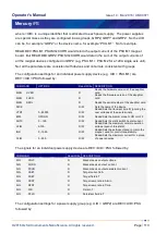
10.3.5.3 Addressing a temperature sensor
To address a temperature sensor, use the following structure:
DEV:<UID>:TEMP
where <UID> is a unique identifier that is allocated to each board, based on its SPI location.
The configuration settings for a temperature sensor are DEV:<UID>:TEMP followed by:
COMMAND
OPTIONS
Read/Write DESCRIPTION
MAN
HVER
R
Reads the hardware version of the daughter
card
MAN
FVER
R
Reads the firmware version of the daughter
card
MAN
SERL
R
Reads the serial number of the daughter card
NICK
R/W
Sets the name of the device
STAT
R
Reads the alarm flags for the device (Hex
Format)
TYPE
DUM:PTC:NTC:TCE:DDE
R/W
Sets the sensor type
EXCT TYPE
UNIP:BIP:SOFT
R/W
Sets the excitation type
EXCT MAG
0 - 1000
R/W
Sets the excitation magnitude
CAL
OFFS
0 - 1000
R/W
Sets the offset of the calibration curve
CAL
SCAL
0 - 1000
R/W
Sets the scale of the calibration curve
CAL
FILE
R/W
Sets the calibration file to use to calculate the
temperature
CAL
INT
NONE:LIN:SPL:LAGR
R/W
Sets the interpolation method for the
calibration file. SPL and LAGR options not yet
implemented.
CAL
HOTL
0 - 2000
R/W
Set the maximum value for temperature
setpoint (hot limit)
CAL
COLDL 0 - 1000
R/W
Set the minimum value for temperature
setpoint (cold limit)
CAL
CAL
R/W
Calibrates the hardware. Reads the time of
the last calibration (seconds since 1970-01-01
00:00:00 UTC)
RSMP
R/W
Signal filter buffer length (number of samples)
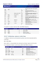
The signals for a temperature sensor are DEV:<UID>:TEMP followed by:
COMMAND
Read/Write DESCRIPTION
SIG
VOLT
R
Sensor voltage
SIG
CURR
R
Sensor current
SIG
TEMP
R
Measured temperature
SIG
RTMP
R
Raw temperature
SIG
POWR
R
Sensor power dissipation
SIG
RES
R
Measured resistance (PTC/NTC)


